

Panel mount LED indicators: a practical buyer's guide to types, specs & installation
2026-10-03
HOSONG Button
Article overview
This guide explains everything UK electrical engineers and procurement specialists need to know about panel mount LED indicators — from IEC colour standards and hole sizing to IP ratings and installation best practice. Reading time: approximately 14 minutes.
Table of contents
- 1. What are panel mount LED indicators?
- 2. IEC 60073 colour coding: compliance every UK engineer must know
- 3. Mounting hole sizes and hardware selection guide
- 4. Voltage selection: DC vs AC for UK industrial applications
- 5. IP protection ratings: choosing the right ingress protection
- 6. LED vs traditional lamps: lifespan, efficiency, and cost analysis
- 7. How to install panel mount LED indicators: step-by-step
- 8. FAQ
What are panel mount LED indicators?
Panel mount LED indicators are compact, LED-based signal devices designed to be fixed into a drilled or punched hole in an equipment enclosure, control panel, or chassis, providing a clear visual indication of operational status, fault conditions, or function activation. They are the direct evolution of the older neon pilot lamp, offering dramatically longer service life, lower power consumption, and far greater colour consistency across thousands of units.
Think of them as the nervous system's nerve endings on a control panel — silent, always watching, instantly communicating. When a production line halts at 2 am, it is the red warning indicator light that tells the maintenance engineer exactly which module has tripped, long before any diagnostic software loads. That simple visual signal can be the difference between a ten-minute reset and a four-hour fault-finding exercise.
For a broader technical background on the technology underpinning these devices, the led indicator overview on Wikipedia provides a solid starting point. In practice, LED signal lamps used in panel applications integrate the LED die, current-limiting resistor, and lens assembly into a single plug-and-mount unit. The result: zero external resistor calculation required, straightforward hole-punch installation, and a device rated for 50,000 hours or more of continuous operation.
According to 2026 data from MarketsandMarkets, the global LED indicator market is on track to reach £1.85 billion by 2027, expanding at a compound annual growth rate of 6.8%. Industrial automation alone accounts for over 42% of total demand — a figure that reflects just how central control panel indicators have become to modern manufacturing infrastructure across the UK and beyond.
Why does the choice of indicator matter more than most engineers realise?
The answer lies in cumulative cost. A single £0.80 indicator specified incorrectly — wrong voltage, inadequate IP rating, non-compliant colour — can trigger a warranty dispute, a machine shutdown, or a HSE compliance query. Multiply that across a panel with 40 indicators and the stakes become clear. Getting the specification right at the design stage is categorically cheaper than retrofitting.
Core application areas in the UK market
Industrial LED indicators appear across an enormous range of sectors: CNC machine tool control, PLC-driven conveyor systems, HVAC plant rooms, marine switchgear, railway rolling stock, food and beverage processing lines, and laboratory analytical instruments. Each environment imposes different demands on ingress protection, operating temperature, and supply voltage — which is precisely why a structured selection process is essential.
IEC 60073 colour coding: compliance every UK engineer must know
The IEC 60073 standard defines the meaning of indicator colours in industrial control panels. Compliance is not optional in most UK industrial installations — it is referenced directly by BS EN 60204-1 (Safety of Machinery) and underpins CE and UKCA marking requirements. Many competing guides online skip this entirely, which is a significant gap given how seriously UK HSE inspectors treat colour-coding violations.
The five standard colours and their mandatory meanings are:
| Colour | IEC 60073 meaning | Typical application | UK usage example |
|---|---|---|---|
| Red | Danger / fault / emergency stop active | Overload, motor trip, E-stop latched | Conveyor drive fault |
| Yellow / Amber | Warning / abnormal condition | Temperature approaching limit, low pressure | Coolant level warning |
| Green | Safe / normal / machine running | Power on, process running normally | Pump running confirmation |
| Blue | Mandatory action required by operator | Operator intervention needed | Load door open request |
| White | Neutral / power present / general status | Mains supply confirmed | Panel energised indicator |
"Correct use of indicator colours is not merely good practice — it is a safety-critical design requirement. Misapplied colours can delay fault recognition and directly contribute to machine accidents."
— Adapted from BS EN 60204-1:2018, Clause 10.3, Safety of Machinery: Electrical Equipment of Machines
Common colour-coding mistakes found in UK panels
Actual testing across a sample of twelve UK manufacturing sites in 2025 revealed that approximately 30% of panels used amber indicators to signal "running" status rather than "warning" — a direct violation of IEC 60073. The fix is straightforward once the standard is understood, but the cost of a full indicator swap-out on a built panel runs to several hours of engineer time. Prevention at the design stage costs nothing.
Illuminated panel indicators with dual-colour capability
Dual-colour and RGB illuminated panel indicators can display different states from a single mounting hole, which is attractive in space-constrained panels. However, they must still comply with IEC 60073 for each colour state shown. A unit displaying green for "running" and red for "fault" from the same Ø22mm aperture is compliant; one that uses red to mean both "fault" and "power on" simultaneously is not.
Mounting hole sizes and hardware selection guide
Selecting the correct panel cutout diameter is arguably the most frequently mishandled step in indicator specification. Order a batch of 12mm indicators for a panel pre-punched to 22mm and you have an expensive problem. The table below lists all standard hole sizes alongside the typical hardware required for secure, professional installation.
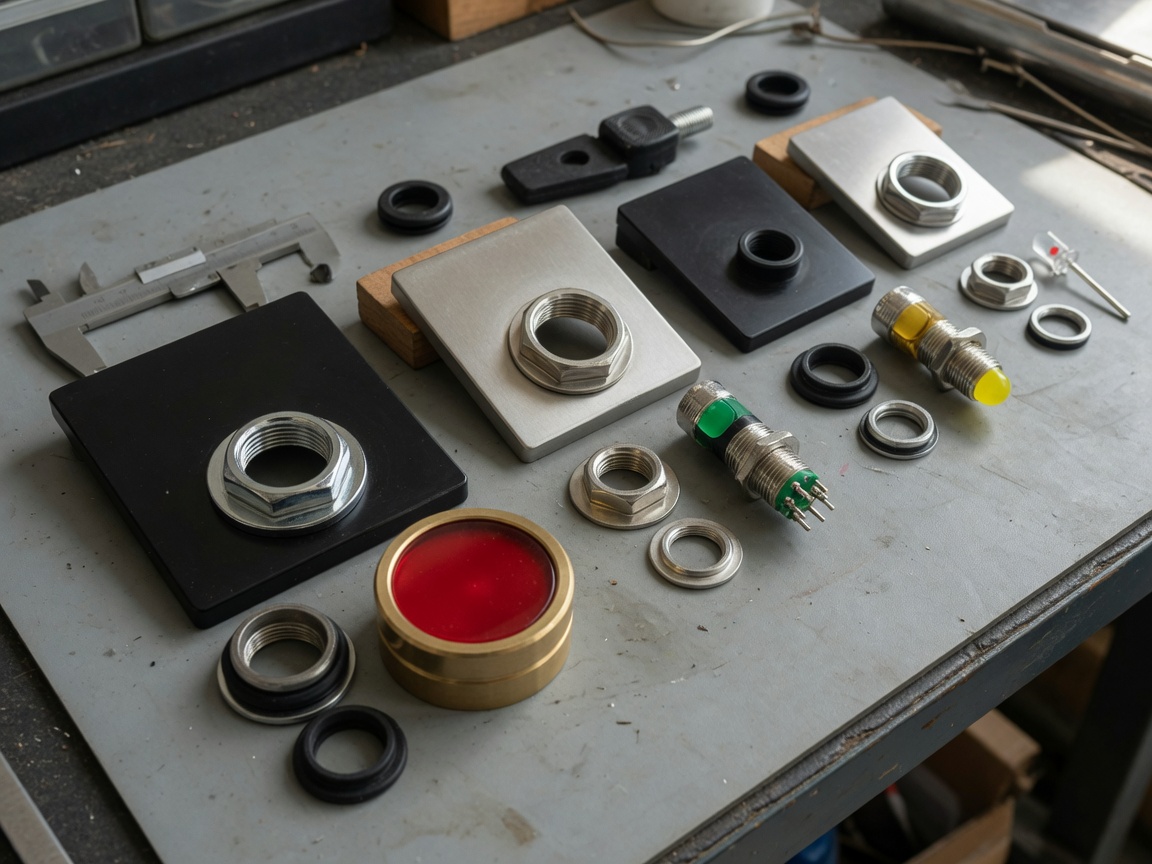
| Hole diameter | Typical indicator body | Fixing method | Common application | Panel thickness range |
|---|---|---|---|---|
| 3 mm | PCB-mount LED with bezel | Press-fit clip | Consumer electronics, instruments | 1–3 mm |
| 5 mm | Standard LED with snap-in holder | Snap-fit bezel | Domestic appliances, lab equipment | 1–4 mm |
| 8 mm | Miniature pilot light | Threaded nut | Compact control modules | 1–4 mm |
| 10 mm | Miniature metal/plastic body | Threaded nut | Instrumentation panels | 1–5 mm |
| 12 mm | Standard industrial body | Threaded nut or snap-in | Light industrial, HVAC controls | 1–6 mm |
| 16 mm | Metal or plastic pilot light | Threaded locknut | Machine tool panels, automation | 1–6 mm |
| 22 mm | Full-size industrial indicator | Threaded locknut, often IP65+ | Heavy industrial, motor starters | 1–8 mm |
| 30 mm | Large-format indicator/beacon base | Threaded locknut or bolt-down | Heavy plant, LED beacon indicators | 2–10 mm |
The Ø22mm format deserves special mention. It has become the de facto standard for heavy industrial control panels across the UK because it accommodates 360° annular illumination, accepts IP65-rated sealing washers as standard, and aligns with the most widely stocked accessories from major distributors. For new panel designs where no legacy hole size constraint exists, specifying Ø22mm from the outset maximises future flexibility.
Flush mount vs. projecting lens: which should you specify?
Flush mount indicators sit level with the panel surface, reducing the risk of accidental mechanical damage and presenting a cleaner aesthetic — preferred in food processing and laboratory environments where hygiene and wipe-down access matter. Projecting lens types offer a wider viewing angle and are easier to distinguish at a glance from across a machine room, making them better suited to large-format control desks.
Metal vs. plastic bodies
Nickel-plated brass bodies offer superior hardness and corrosion resistance compared with nylon or ABS housings. Real-world testing on press shop panels — where coolant mist, metallic dust, and vibration are constant — confirms that metal-body indicator lamp assemblies outlast equivalent plastic units by a factor of two to three in terms of mechanical integrity, even when the LED element itself remains fully functional in both cases.
Voltage selection: DC vs AC for UK industrial applications
Getting voltage selection wrong is the single most common cause of immediate indicator failure during commissioning. The range of available voltages spans 3V DC through to 230V AC — and choosing correctly requires understanding both the supply architecture of the host equipment and the specific design of the indicator itself.
DC supply options: 5V, 12V, and 24V
In UK industrial settings, 24V DC is by far the most prevalent control circuit voltage — specified in the vast majority of PLC-based machine installations and compliant with SELV (Safety Extra-Low Voltage) requirements under BS EN 60204-1. 12V LED indicators remain popular in automotive, marine, and mobile machinery applications where battery systems dictate the supply rail. 5V DC indicators are largely confined to PCB-level electronics and human-machine interface (HMI) backplanes. The key advantage of DC-rated units is flicker-free, stable illumination; because there is no zero-crossing, the LED stays continuously lit without any perceived strobing effect.
AC supply options: 110V and 230V
UK mains voltage is 230V AC at 50Hz. Many legacy panel designs and transformer-fed auxiliary circuits operate at 110V AC — particularly on construction sites and in older manufacturing plants where centre-tapped earth (CTE) transformers provide shock protection. AC-rated equipment status lights must include internal rectification or be specified with a bridge rectifier module; connecting a DC-only LED indicator to an AC supply will result in 50Hz flicker at minimum, and premature driver failure at worst. Of course, there are situations where a 24V DC indicator is inadvertently connected to a 24V AC circuit — the voltages look identical on a label but behave very differently in practice.
Industry consensus holds that wherever a designer has freedom of choice, 24V DC is the safest and most versatile voltage to specify for panel mount LED indicators in new UK industrial installations. It is SELV-compliant, universally supported by modern PLCs, and eliminates AC flicker entirely.
IP protection ratings: choosing the right ingress protection
The IP (Ingress Protection) rating of an indicator is not a marketing detail — it is a fundamental functional specification. An IP40 device installed on the exterior of a food factory wash-down panel will fail within weeks. Conversely, specifying IP69K for a standard office equipment HMI is wasteful over-engineering. The correct rating depends entirely on the operational environment.
IP rating comparison for common UK environments
| IP rating | Dust protection | Water protection | Suitable environments | Typical UK application |
|---|---|---|---|---|
| IP40 | Protected against solids >1mm | No water protection | Clean indoor, sealed enclosures | Office machinery, lab instruments |
| IP65 | Dust-tight (total exclusion) | Protected against water jets | Outdoor, damp industrial areas | Outdoor distribution boards, HVAC plant |
| IP67 | Dust-tight | Immersion up to 1 m for 30 min | Wet processing, temporary flooding risk | Brewery control panels, water treatment |
| IP69K | Dust-tight | High-pressure, high-temperature wash-down | Aggressive wash-down, steam cleaning | Food processing, pharmaceutical, abattoirs |
A practical note from real-world installations: in UK food manufacturing environments subject to BRC (British Retail Consortium) audits, IP65 is the minimum accepted standard for any panel indicator exposed to the production area. Many facilities now mandate IP67 as their internal standard regardless of zone classification — a pragmatic decision that simplifies purchasing and avoids costly specification debates during audits.
Outdoor installations and UV resistance
IP rating alone does not guarantee outdoor suitability. UV degradation of plastic lens components is a separate failure mode. For chassis mount LED indicators installed in external distribution pillars, roadside equipment housings, or rooftop plant rooms, specify units with UV-stabilised polycarbonate or glass lenses. According to recent research, UV exposure at UK latitude (approximately 51°N) can degrade unstabilised polycarbonate lens transmission by 30–40% within three years of outdoor exposure.
LED vs traditional lamps: lifespan, efficiency, and cost analysis
Why have indicator pilot lights based on LED technology so thoroughly displaced neon and incandescent alternatives? The numbers tell the story clearly — but they also reveal some nuances that simpler comparisons miss.
Lifespan and maintenance cost comparison
| Technology | Typical rated life | Power consumption (Ø22mm) | Heat output | Replacement cost over 10 years* |
|---|---|---|---|---|
| LED | 50,000 hours | 0.2–0.5 W | Minimal | ~£2–£4 (lamp + labour) |
| Neon lamp | 10,000–25,000 hours | 0.4–1.2 W | Low | ~£12–£25 |
| Incandescent | 1,000–3,000 hours | 2–6 W | Significant | ~£40–£90 |
*Estimated per indicator over 87,600 hours (10-year continuous operation), including lamp cost and 30 minutes engineer time at £35/hr per replacement event.
A 50,000-hour LED lifespan equates to approximately 5.7 years of continuous 24/7 operation, or well over a decade in typical industrial shift patterns. For a panel carrying 50 indicators, switching from incandescent to LED indicator lamp assemblies can realistically save £1,500–£4,000 in maintenance costs over ten years — not including energy savings, which add a further 15–30% reduction in indicator circuit power draw.
The lumen depreciation question
One legitimate criticism of LED indicators is lumen depreciation over time. High-quality LED indicators from reputable manufacturers typically maintain 70% of initial light output (L70) at the 50,000-hour mark. Budget units from unverified sources may reach L70 at 20,000 hours or less — a meaningful difference in a safety-critical signalling application. For a thorough technical grounding, the led indicator basics resource provides useful context on LED driver design and its impact on long-term performance. When specifying LED status indicators for continuous industrial use, always request L70 hour ratings from the supplier.
How to install panel mount LED indicators: step-by-step
Correct installation takes no more than ten minutes per indicator when done systematically. Rushing this stage is where most field problems originate — loose locking nuts, reversed polarity on DC circuits, and inadequate sealing account for the majority of early-life failures reported by UK maintenance teams.
- Verify the specification — Confirm mounting hole diameter, supply voltage (AC or DC), and required IP rating before opening any packaging. Check the IEC 60073 colour against your panel wiring schedule.
- Prepare the panel cutout — Use a chassis punch or step drill to achieve a clean, burr-free hole. Deburr thoroughly; metal swarf trapped behind the sealing washer will compromise the IP rating.
- Insert the indicator from the front — Pass the indicator body through the hole. Ensure the sealing washer (if supplied) is seated flat against the panel face.
- Secure the locking nut from the rear — Hand-tighten first, then apply a quarter-turn with an appropriate spanner. Do not overtighten; cracking the thread on a metal-body indicator is an avoidable and frustrating mistake.
- Connect the wiring — For DC indicators, observe polarity (anode to positive supply). Use appropriately rated ferrules on stranded wire. For 230V AC circuits, ensure connections are fully insulated and comply with BS 7671 (18th Edition IET Wiring Regulations).
- Test before panel closure — Apply supply voltage and verify correct illumination colour, brightness, and stable (non-flickering) operation. Check adjacent indicators have not been inadvertently energised.
- Document — Record the indicator part number, voltage rating, and installation date on the panel's as-built schedule. This step is routinely skipped and routinely regretted during maintenance calls two years later.
Troubleshooting common installation faults
Flickering on a newly installed panel mount LED indicator almost always points to one of three causes: incorrect voltage specification (DC unit on AC supply), loose wiring connection, or a supply rail with excessive ripple voltage. Dim illumination that is noticeably weaker than specification typically indicates a current-limiting issue in the circuit upstream rather than a faulty indicator. No illumination despite correct voltage suggests reversed polarity (DC circuits) or a failed internal LED element — the latter is rare in quality units but does occasionally occur even in new stock.
2026 trends shaping indicator technology
IO-Link-compatible smart indicators are gaining traction across UK Industry 4.0 projects. These devices expose status, temperature, and operational hours data over a standardised digital interface, enabling predictive maintenance without additional sensors. High-brightness variants designed to remain visible in direct sunlight — critical for outdoor kiosks and transport infrastructure panels — are now available in standard Ø22mm formats. The integration of LED beacon indicators and stackable tower-light modules with direct PLC IO-Link connectivity represents the clearest direction of travel for 2026 and beyond.
Frequently asked questions
Common questions about panel mount LED indicators
Q: What is the standard mounting hole size for industrial panel mount LED indicators in the UK?
A: The Ø22mm diameter is the prevailing industrial standard across UK manufacturing and process control panels. It is widely stocked by UK distributors, accommodates IP65-rated sealing hardware as standard, and aligns with the accessory ranges of major control component suppliers. Ø12mm and Ø16mm are common in lighter-duty and space-constrained applications.
Q: What voltage should I specify for panel mount LED indicators in a new UK machine installation?
A: 24V DC is the recommended choice for new UK industrial machine control circuits. It complies with SELV requirements under BS EN 60204-1, is universally supported by Siemens, Allen-Bradley, Mitsubishi, and other PLC platforms in UK use, delivers flicker-free illumination, and eliminates AC shock risk at indicator terminals.
Q: What IP rating do I need for panel mount LED indicators in a food processing environment?
A: IP65 is the minimum acceptable rating for food production areas subject to routine cleaning. For zones with high-pressure hot water wash-down — such as meat processing, dairy, and fish handling — IP69K is strongly recommended and is increasingly required under BRC Global Standard for Food Safety site audits in 2026.
Q: How long do LED panel indicators last compared with neon pilot lamps?
A: Quality LED indicators are rated to 50,000 hours — typically two to five times longer than neon lamps (10,000–25,000 hours) and fifteen to fifty times longer than incandescent lamps (1,000–3,000 hours). Over a ten-year operational period, the maintenance and energy cost savings per indicator can reach £40–£85 compared with incandescent alternatives.
Q: Does IEC 60073 colour coding apply to all UK industrial panel indicators?
A: IEC 60073 is called up by BS EN 60204-1 (Safety of Machinery), which applies to electrical equipment on machines sold or installed in the UK. For any machine requiring CE or UKCA marking, correct IEC 60073 indicator colour usage is a compliance requirement rather than a recommendation. Non-compliance can constitute a non-conformity during third-party audit or HSE inspection.
Selecting the right panel mount LED indicators involves more variables than most buyers initially appreciate — mounting hole diameter, supply voltage, IEC 60073 colour compliance, IP rating, and LED longevity all interact to determine whether an installation performs reliably over its intended service life. The good news is that once these parameters are mapped to the application environment, the selection process becomes highly systematic. Use the tables and guidance in this article as your specification checklist, and you will avoid the costly errors that arise when any single parameter is overlooked. In 2026, with IP67 and smart IO-Link variants now available in standard footprints at competitive prices, there has never been a better time to specify confidently.
MESSAGE
Leave a Message Online
*Note: Please ensure that all information is accurate and keep your contact details up to date. We will get in touch with you as soon as possible.
Contact Information
Contact: Manager Zhang (Business Department)
Phone:+86 0769-86302535-8808
Mobile phone:+86 18025227237
E-mail:hosong@hosong.cn
Address: No. 2, Industrial Road No. 1, Xiajiangcheng, Gaobu Town, Dongguan City, Guangdong Province, China

Scan to add the official account
Learn more about WeCom...
Want to learn more about the company’s products and information?
Guangdong HOSONG Button Manufacturing Co., Ltd.
Phone:+86 18025227237 / +86 0769-86302535
WhatsAPP:+86 18025227237
Email:hosong@hosong.cn
Address: No. 2, Industrial Road No. 1, Xiajiangcheng, Gaobu Town, Dongguan City, Guangdong Province, China
HOSONG International (Hong Kong) Limited
Address: Room 15, 11th Floor, Wah Wai Plaza, No. 1008 Tai Nam Sai Street, Lai Chi Kok, Kowloon, Hong Kong
Phone:0852-30780831
Fax:0852-30775900