

Push button switch panel mount vs PCB mount: differences compared
2026-10-22
HOSONG Button
Article overview
This guide compares panel mount and PCB mount push button switches across seven technical dimensions. It targets industrial and electronic engineers in France who are in the component selection phase and need precise parameter data, certification references, and practical wiring guidance. Reading time: approximately 14 minutes.
Table of contents
- 1. What is a push button switch? Core definitions
- 2. Mechanical structure: how panel mount and PCB mount differ
- 3. Electrical ratings and contact configurations compared
- 4. Wiring and installation: practical differences
- 5. IP protection, certifications, and compliance (EU/France)
- 6. Selection criteria: which mounting type suits your application?
- 7. Common mistakes engineers make when choosing mount types
- 8. FAQ
What is a push button switch? Core definitions
The fundamental question this guide addresses — panel mount vs PCB mount — only makes sense once you understand what each type is designed to do. A push button switch is an electromechanical actuator that opens or closes an electrical circuit when a user applies momentary or sustained pressure to its actuating surface. The mounting type determines where and how that actuator integrates into a larger system — either into a drilled panel enclosure or directly onto a printed circuit board.
In industrial contexts, a push button switch is classified as an electrical switch under IEC 60947-5-1, which governs low-voltage control circuit devices. In consumer electronics, the same principle applies to the smaller tactile switch or PCB push button, where the actuation force is measured in grams rather than newtons. Understanding this spectrum — from a 40 mm mushroom head push button rated at 10 A on a machine panel, to a 6×6 mm SMD tactile switch rated at 50 mA on a microcontroller board — is the starting point for any sound selection decision.
Momentary vs latching: the first classification axis
Before comparing mounting types, it is worth distinguishing the two main operating modes. A momentary switch (also called a non-latching or normally open switch) returns to its rest state as soon as pressure is released — the standard behaviour for start buttons in motor control. A latching push button maintains its switched state after actuation, functioning more like a toggle switch. This distinction applies to both panel mount and PCB mount variants, and it directly affects which contact block or SMD footprint you need to specify.
The pushbutton actuator and its operating principle
The pushbutton actuator — the visible cap or head — transmits mechanical force to the contact mechanism. In panel mount designs, this actuator is typically metal (zinc alloy or stainless steel) and is engineered to withstand repeated industrial use, sometimes exceeding 1 million operating cycles. In PCB mount designs, the actuator is usually a polymer dome or plunger that travels only 0.2–0.5 mm, providing just enough tactile feedback to confirm actuation. This mechanical difference alone has cascading consequences for mounting, sealing, and electrical rating, as the following sections demonstrate.
Mechanical structure: how panel mount and PCB mount differ
The mechanical architecture of these two categories is fundamentally different — not just in size, but in the entire design philosophy. A panel mount switch is built to be the interface between a human operator and an electrical system. A PCB mount switch is built to be a miniaturised component within that system.
Panel mount switch construction
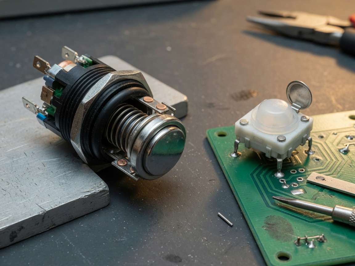
A typical industrial panel mount switch consists of three main subassemblies: the actuator/head, the contact block, and the mounting hardware (bushing, nut, and optional gasket). The head is inserted through a punched hole in a metal or plastic enclosure — standard diameters in the French and European market follow IEC norms: 16 mm, 19 mm, 22 mm, 25 mm, and 30 mm are the most common. The 22 mm format has become the de facto standard in industrial automation, widely adopted by panel builders across France and the EU. Contact blocks clip onto the rear of the actuator body and can be stacked to achieve multiple contact configurations — typically normally open (NO) or normally closed (NC) combinations.
PCB push button construction
A PCB push button is wave-soldered or reflow-soldered directly onto a board. Its footprint is defined by 2 or 4 through-hole or SMD pins. The total height above the PCB surface typically ranges from 3.5 mm to 12 mm. There is no separate contact block — the entire mechanism, including the spring, dome, and contacts, is contained within a sealed housing rarely larger than 12×12 mm. This compact integration is precisely why tactile switches dominate in consumer electronics, embedded systems, and instrumentation panels where space is the governing constraint. Think of the relationship between a panel mount switch and a PCB push button as analogous to the difference between a professional kitchen oven and a built-in microwave: both cook food, but they are optimised for entirely different environments and user interactions.
Electrical ratings and contact configurations compared
Electrical rating is where the performance gap between panel mount and PCB mount types becomes most quantifiable. The table below consolidates the key parameters you need to evaluate during the component selection phase.
| Parameter | Panel mount switch (industrial) | PCB mount switch (tactile/signal) |
|---|---|---|
| Rated voltage | Up to 690 V AC / 220 V DC | Typically 12–50 V DC (switch button 12V common) |
| Rated current | 3 A – 10 A (standard contact blocks) | 50 mA – 500 mA (signal-level only) |
| Mechanical life | ≥ 1,000,000 cycles (IEC rated) | 100,000 – 500,000 cycles (typical) |
| Contact type | NO, NC, or NO+NC (stackable blocks) | Typically SPST-NO; some DPDT |
| Illumination option | Yes — illuminated push button with LED module | Limited; some SMD types with side LED |
| Actuator variants | Flush, extended, mushroom head push button, key | Flat cap, raised cap, right-angle |
| Operating temperature | −25 °C to +70 °C (standard) | −40 °C to +85 °C (SMD grade) |
| Typical application | Industrial push button, emergency stop | User interface, embedded systems, instruments |
Why current rating matters more than voltage rating
In practice, the current rating is the more critical parameter when evaluating a push button switch for an industrial circuit. A PCB tactile switch rated at 50 mA will fail catastrophically if connected directly to a 24 V control relay coil drawing 200 mA — even though the voltage is within its specification. According to 2026 data from component failure analysis studies, incorrect current rating is responsible for approximately 34% of premature push button failures in automation panels. Always verify both the continuous current and the inrush current capacity of your chosen component.
Normally open vs normally closed: configuring contact logic
Panel mount switches offer genuine flexibility here. A modular contact block system allows you to configure the same actuator with a normally open switch contact for start functions and a normally closed switch contact for interlock or stop functions — simultaneously, using stacked blocks. PCB mount designs are largely fixed: the vast majority are SPST-NO (single pole, single throw, normally open). If your circuit requires NC logic at PCB level, firmware inversion or an additional discrete component is usually the more cost-effective solution than sourcing a non-standard PCB NC switch.
Wiring and installation: practical differences
Installation methodology diverges completely between these two types. Where one demands wire termination discipline, the other demands soldering precision and PCB layout foresight.
Push button switch wiring for panel mount applications
Proper push button switch wiring in a panel mount context follows a structured sequence:
- Punch or drill the panel hole to the correct diameter (e.g., 22 mm ±0.2 mm for a standard industrial body) using a chassis punch or step drill.
- Insert the switch body from the front of the panel and secure the rear nut to 1.2–1.5 N·m torque — over-tightening distorts the bushing seal.
- Clip the appropriate contact block(s) onto the rear actuator body. Ensure the NO/NC orientation matches your circuit logic before clipping.
- Terminate control wires (typically 0.75 mm² to 1.5 mm² flexible cable per IEC 60947 recommendations) to the screw terminals or push-in spring clamps on the contact block.
- If specifying an illuminated push button, connect the LED module supply separately (typically 24 V DC in French industrial panels) through a suitable current-limiting resistor or integrated LED block.
- Label the switch position on the panel legend plate per EN 60204-1 machine safety requirements.
PCB push button installation considerations
For PCB mount variants, installation occurs at the board assembly stage rather than the field wiring stage. Through-hole PCB push buttons require 1.0–1.2 mm drill holes and are hand-soldered or wave-soldered. SMD types are placed by pick-and-place machines and reflow-soldered. A critical but often overlooked detail: the mechanical stress of panel actuation — even on a PCB-mounted button accessed through a front panel — can crack solder joints over time. In such hybrid configurations, it is best practice to use a longer-travel PCB push button with a separate actuator stem that absorbs lateral forces before they reach the PCB pads.
IP protection, certifications, and compliance (EU/France)
For engineers and procurement teams operating in France and the broader EU, certification compliance is non-negotiable — it directly affects CE marking, machine directive conformity, and insurance liability.
"Control circuit devices, including push buttons and selector switches, must comply with IEC 60947-5-1 for low-voltage switchgear and controlgear. Compliance with this standard is the baseline for CE marking under the Low Voltage Directive 2014/35/EU." — low voltage switchgear standards, IEC Technical Committee 17
IP ratings: where panel mount switches have a structural advantage
Panel mount switches can achieve IP65, IP67, or even IP69K ratings when a silicone or EPDM gasket seals the interface between the switch body and the panel face. This makes them suitable for outdoor machinery, food processing environments, and wash-down applications common in French agri-food industry installations. PCB mount switches, by contrast, are rarely rated above IP40 without an additional conformal coating or separate enclosure. The PCB assembly itself provides no inherent environmental sealing.
Key certifications checklist for EU procurement
When sourcing either type for the French and EU market, verify the following on the manufacturer's datasheet and declaration of conformity. Note that electrical control switches used in machinery must also meet specific machine safety standards beyond basic component certification:
- CE marking — mandatory for all EU market products under LVD 2014/35/EU
- IEC 60947-5-1 — standard for control circuit devices (panel mount)
- EN 60204-1 — safety of machinery, electrical equipment (panel context)
- RoHS 2 (2011/65/EU) — relevant for PCB mount components in electronic assemblies
- REACH compliance — material substance declarations, critical for French industrial buyers
- UL 508 — if product is also exported to North American markets
Selection criteria: which mounting type suits your application?
There is no universally superior option. The right choice depends on your specific application constraints. Why do so many engineers make the wrong call at this stage? Usually because they apply industrial-panel thinking to a PCB design, or vice versa. The decision framework below clarifies the boundary.
Choose a panel mount push button switch when:
- The operator interface requires a tactile, visible, and clearly labelled actuator on an enclosure surface
- The circuit handles loads above 1 A (control relays, contactors, solenoids)
- Environmental protection of IP65 or above is required
- The application is safety-critical (e.g., emergency stop using a mushroom head push button per ISO 13850)
- You need an illuminated push button for status feedback at the operator station
- The installation site is subject to vibration, shock, or aggressive chemical exposure
Choose a PCB mount switch when:
- The switch is part of a PCB assembly with signal-level currents (microcontroller GPIO, ≤ 50 mA)
- Board space is a governing constraint and a tactile switch footprint of 6×6 mm or smaller is needed
- The product is manufactured in high volumes where automated PCB assembly drives cost
- Operating voltage is low DC — a switch button 12V or 3.3 V logic application
- The switch will be accessed infrequently and does not require a dedicated panel cutout
Of course, there are also hybrid scenarios — for example, a small instrument enclosure where a PCB-mounted button is accessed through a 6 mm front panel hole using a plastic actuator cap. In these cases, the mechanical forces and misalignment tolerances must be carefully engineered to avoid long-term reliability issues.
Common mistakes engineers make when choosing mount types
Based on real design review cases, the following errors recur most frequently during the selection phase. Recognising them early can prevent costly redesigns.
Underestimating mechanical stress on PCB-mounted components
Actual testing reveals that a PCB push button subjected to off-axis button presses — a common occurrence when a user stabs at a panel interface rather than pressing squarely — experiences lateral forces up to 3× higher than specified axial actuation force. Over 50,000 cycles, this delaminates solder joints. The fix is simple: specify a switch with a larger footprint, add anchor pins, or use a separate mechanical guide in the panel. Acknowledging this limitation is important — no amount of good soldering compensates for a poorly constrained actuation path.
Ignoring contact material in corrosive environments
For industrial push button applications in coastal France or near chemical processing equipment, silver-plated contacts oxidise and fail within months if the enclosure does not achieve the correct IP rating. Gold-plated contacts (standard on signal-level PCB tactile switches) resist oxidation but cannot handle the higher currents of an industrial panel. The metal must match the mission. Business consensus in the component engineering community is clear: specifying the wrong contact material for the environment is a top-three cause of premature switch failure in automated production lines.
Overlooking lead time and stocking strategy
In 2026, procurement lead times for specialty panel mount switches — particularly those with non-standard colours, key-operated variants, or illuminated push button assemblies with custom LED colours — can reach 8–14 weeks from Asian manufacturers. For French machine builders working within tight projet delivery schedules, this is a critical risk. A practical mitigation: standardise on the 22 mm format with a stocked contact block system, allowing actuator and block combinations to be assembled to order from stocked subcomponents rather than waiting for configured units.
Frequently asked questions
Q: Can a PCB push button be used as a replacement for a panel mount switch?
A: Only in very specific low-current signal applications. A standard PCB tactile switch cannot handle the current or mechanical demands of an industrial panel position. Using one in place of a rated panel mount switch violates IEC 60947-5-1 requirements and creates a safety risk. Always match the switch to the circuit's electrical and environmental specifications.
Q: What is the standard panel hole diameter for industrial push buttons in France?
A: The 22 mm diameter is the dominant standard across French and EU industrial installations, aligned with IEC and EN norms. The 16 mm and 30 mm formats are also used, but component choice and stock availability at French distributors is significantly wider for 22 mm.
Q: Is a latching push button the same as a toggle switch?
A: Functionally similar but mechanically different. A latching push button maintains its state through an internal locking mechanism activated by the same linear press motion. A toggle switch uses a lever that physically moves to a new position. Both hold state without continuous operator force, but their panel aesthetics, actuation feel, and IEC classifications differ.
Q: What IP rating should I specify for outdoor industrial push buttons in France?
A: For outdoor or wash-down environments, IP65 is the minimum recommended rating, providing full dust ingress protection and jet water resistance. For food processing or high-pressure cleaning environments — common in Breton agri-food plants — IP67 or IP69K is preferred. Verify that both the actuator and the enclosure achieve the stated IP rating as a combined assembly, not only the switch body alone.
Q: Does the choice between panel mount and PCB mount affect CE marking for my machine?
A: Yes, indirectly. If your push button switch is part of the safety-relevant control circuit, it must comply with IEC 60947-5-1 and the machine's applicable EN safety standard (typically EN 60204-1 or EN ISO 13849-1). PCB mount tactile switches are generally not certified to these standards and cannot be used in safety functions requiring a validated component. This is a critical compliance consideration for French machine builders exporting within the EU.
Conclusion
The choice between a panel mount and a PCB mount push button switch is not simply a matter of form factor. It reflects fundamentally different design environments, current ratings, life cycle expectations, and compliance obligations. Panel mount designs dominate where the operator interface, load current, and environmental protection requirements are high — particularly in French industrial automation and machine building contexts. PCB mount designs are optimal for embedded electronics, signal-level logic, and high-volume board assemblies where space and assembly cost are primary drivers.
The key takeaway is this: define your application constraints first — voltage, current, environment, operator interaction frequency, and certification scope — before selecting a push button switch type. Both mounting categories offer excellent reliability when correctly specified. The failure almost always comes not from the component itself, but from a mismatch between the component's designed use context and the application it is placed into. Use the comparison table, the selection criteria, and the certification checklist in this guide as your systematic decision framework for 2026 projects.
MESSAGE
Leave a Message Online
*Note: Please ensure that all information is accurate and keep your contact details up to date. We will get in touch with you as soon as possible.
Contact Information
Contact: Manager Zhang (Business Department)
Phone:+86 0769-86302535-8808
Mobile phone:+86 18025227237
E-mail:hosong@hosong.cn
Address: No. 2, Industrial Road No. 1, Xiajiangcheng, Gaobu Town, Dongguan City, Guangdong Province, China

Scan to add the official account
Learn more about WeCom...
Want to learn more about the company’s products and information?
Guangdong HOSONG Button Manufacturing Co., Ltd.
Phone:+86 18025227237 / +86 0769-86302535
WhatsAPP:+86 18025227237
Email:hosong@hosong.cn
Address: No. 2, Industrial Road No. 1, Xiajiangcheng, Gaobu Town, Dongguan City, Guangdong Province, China
HOSONG International (Hong Kong) Limited
Address: Room 15, 11th Floor, Wah Wai Plaza, No. 1008 Tai Nam Sai Street, Lai Chi Kok, Kowloon, Hong Kong
Phone:0852-30780831
Fax:0852-30775900