

Switch on off push button: how to choose and wire the right one for your project
2026-10-07
HOSONG Button
Article overview
This guide explains what a switch on off push button is, compares all major types with real specification data, provides UK-specific 230 V wiring guidance, covers UKCA and BS EN 60947-5-1 compliance requirements, and delivers a practical decision framework for electricians, engineers and advanced DIY enthusiasts purchasing in the UK market.
Table of contents
- 1. What is a switch on off push button?
- 2. Types of push button switch explained
- 3. Momentary vs latching: a structured comparison
- 4. UK wiring guide for 230 V AC circuits
- 5. UK compliance: UKCA, BS EN 60947-5-1 and PUWER 1998
- 6. Accessibility and illumination: BS 8300 considerations
- 7. How to choose the right switch for your application
- 8. Frequently asked questions
What is a switch on off push button?
A switch on off push button is a manually actuated electrical component that opens or closes a circuit when physically pressed, providing direct on/off control of power or signal flow in consumer, commercial and industrial applications.
At its most basic level, it is a push button switch mechanism — a set of electrical contacts mounted inside a housing, brought together or separated by a spring-loaded actuator. Press it and something happens: a motor starts, a light turns on, a conveyor stops. Release it and the circuit either reverts to its original state (momentary contact switch) or holds its new state (latching push button switch). That single distinction — momentary versus maintained — is the first design decision every engineer or electrician must make.
Why do so many people get this wrong? Often because the visual appearance of a momentary push button and a latching push button is nearly identical. Without checking the datasheet, it is easy to install the wrong type and spend hours troubleshooting unexpected circuit behaviour.
The anatomy of a push button switch
A typical panel mount push button consists of five key elements: the actuator (the part you press), the return spring, the contact block, the terminal screws or solder lugs, and the mounting collar or bezel. The contact block is where the electrical work actually happens. It contains at least one normally open (NO) contact — open at rest, closed when pressed — or a normally closed (NC) contact — closed at rest, opened when pressed. Many industrial push buttons offer both NO and NC contacts simultaneously, which is essential for interlock circuits. The actuator travel distance, typically between 2 mm and 6 mm depending on the series, directly affects tactile feedback and operator confidence, a detail we will return to in the accessibility section.
Where are they used?
The applications are genuinely vast. In a domestic setting, an on off power button switch controls a boiler, a garage door motor, or a doorbell circuit. In light commercial buildings, illuminated push button switches indicate HVAC system status on DIN rail control panels. On a factory floor, heavy-duty industrial push buttons — often with a mushroom head push button actuator — serve as machine start/stop controls or emergency stops. According to recent 2026 industry data, automation and industrial control account for over 38% of global push button switch demand, making it the single largest application segment.
Types of push button switch explained
Understanding the full taxonomy is essential before comparing specifications. Each sub-type solves a specific engineering problem, and selecting the wrong category is a costly mistake.
Momentary and latching types
The momentary push button switch — also called a push to make switch or push to break switch depending on its default contact state — is the most common type in control circuits. Press it, the circuit changes state; release it, the circuit reverts. A standard doorbell uses a push to make switch: the circuit is open at rest and closes only while the button is held. Contrast this with the latching push button switch (sometimes called a maintained or self-locking switch): one press closes the circuit, a second press opens it. Think of the power button on older desktop computers — it stays in the depressed position until pressed again. Both types are available as panel mount push buttons with standard 22 mm cutout dimensions, the most widely used format in UK industrial enclosures.
Illuminated, mushroom head and specialist variants
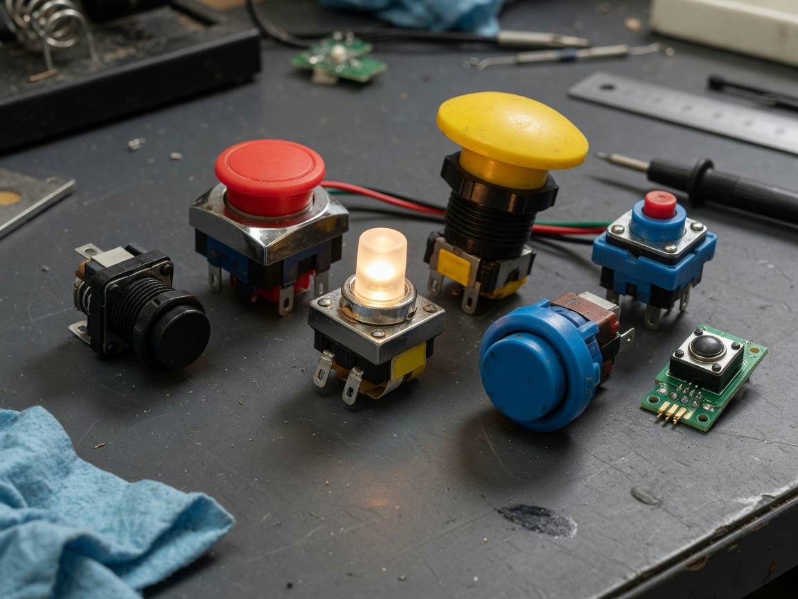
The illuminated push button switch integrates an LED — most commonly red, green, amber or white — directly into the actuator cap. This serves a dual purpose: it confirms circuit status at a glance and improves visibility in low-light environments. A power illuminated push button is an exclusive main power control switch for small precision equipment, while a heavier-rated power illuminated push button is a dedicated heavy-duty main power switch for large industrial units. A third variant — a push button with annular and power symbol lights — is specially developed for main power control of industrial equipment, providing both ring illumination and a clear power symbol for intuitive operator recognition.
The mushroom head push button (also known as the palm button or extended actuator) provides a larger strike surface, making it suitable for emergency stop (E-stop) applications or environments where operators wear heavy gloves. The reset push button switch is a spring-return type, often yellow or blue, used to acknowledge and clear fault conditions in machine safety circuits. For environments exposed to moisture, dust or washdown, IP65 or IP67 rated switches are the minimum requirement.
Momentary vs latching: a structured comparison
This is the comparison that competing guides consistently fail to provide in structured form. The table below covers the parameters that actually matter at the selection stage, using typical UK market data from 2026.
| Parameter | Momentary push button | Latching push button |
|---|---|---|
| Circuit action | Spring-return; contact held only while pressed | Maintained; contact held after release |
| Typical contact | NO or NC, or NO+NC | NO+NC (change-over common) |
| Common applications | Doorbells, motor start/stop, reset, jog control | Machine power on/off, conveyor enable, pump control |
| Typical IP rating | IP40–IP67 depending on housing | IP40–IP67 depending on housing |
| Mechanical life | 500,000–2,000,000 operations | 100,000–500,000 operations |
| Voltage rating | Up to 690 V AC (industrial); 3–24 V DC (tactile) | Up to 690 V AC (industrial) |
| UK price range (22 mm panel) | £2.50–£18 (standard); £20–£60 (IP67 illuminated) | £4–£25 (standard); £25–£75 (IP67 illuminated) |
| BS EN 60947-5-1 applicability | Yes — control circuit devices | Yes — control circuit devices |
Reading the normally open / normally closed convention
The normally open normally closed switch labelling trips up beginners and experienced engineers alike. "Normal" refers to the de-energised, at-rest state of the switch — not what happens most often in practice. A normally open (NO) contact is open when the button is not pressed; current cannot flow. A normally closed (NC) contact is closed at rest; current flows until the button is pressed. For a motor start circuit, you typically wire the start button through an NO contact and the stop button through an NC contact. Mixing these up is one of the most common faults on new panel builds.
Tactile push buttons: PCB-mount vs panel-mount
A tactile push button (tact switch) is a miniaturised momentary contact switch designed for PCB mounting, with actuator travel as short as 0.25 mm and contact force between 100 g and 350 g. These are the small, clicky buttons found on consumer electronics, instrument panels and microcontroller development boards. They operate at low voltages — typically 3.3 V or 5 V DC — and are fundamentally different from the 22 mm panel mount push button used in industrial control panels. Confusing the two when specifying a bill of materials is an error worth avoiding explicitly.
UK wiring guide for 230 V AC circuits
Wiring a switch on off push button correctly in a UK 230 V AC installation requires understanding both the circuit topology and the correct terminal identification. Most guides available online default to American 120 V conventions — which is not only unhelpful but potentially dangerous for UK electricians working to BS 7671 (the IET Wiring Regulations).
Basic 230 V momentary start/stop circuit
The following steps describe wiring a two-button (start/stop) motor control circuit on a DIN rail panel, the most common configuration in UK light industrial settings:
- Isolate the supply — switch off the MCB or isolator feeding the panel and verify with a calibrated voltage tester (GS38-compliant probes are mandatory for UK live working).
- Identify the control transformer output — most UK panels use a 230 V / 24 V AC control transformer; the push buttons operate at 24 V AC to reduce shock risk and enable smaller cable cross-sections (typically 0.75 mm²).
- Wire the STOP button (NC contact) — connect the 24 V live supply rail to one terminal of the NC contact on the stop button; connect the other terminal to one terminal of the START button.
- Wire the START button (NO contact) — from the second terminal of the NC stop contact, connect to the NO contact of the start push button; connect the other NO terminal to the coil A1 terminal of the contactor.
- Wire the holding contact — connect an auxiliary NO contact on the contactor in parallel with the start push button terminals; this provides the self-holding (seal-in) function so the motor runs after the start button is released.
- Connect coil return — the A2 terminal of the contactor coil connects back to the 24 V neutral (0 V) rail.
- Earth all metalwork — the metal panel mount push button bezel and enclosure must be bonded to the protective earth bar (PE), coloured green/yellow, per BS 7671 Chapter 41.
- Test before energising — use a continuity tester to verify the NC stop contact is closed at rest and the NO start contact is open at rest before applying power.
"Control circuit devices — including push buttons — installed on UK machinery must comply with BS EN 60947-5-1 and the broader requirements of the Supply of Machinery (Safety) Regulations 2008. Post-Brexit, UKCA marking has replaced CE marking for products placed on the GB market; installers and panel builders should verify that switch assemblies carry the appropriate conformity mark before commissioning."
— Guidance summary aligned with the Health and Safety Executive (HSE) and IET Wiring Regulations 18th Edition
Illuminated push button wiring
An illuminated push button switch adds one extra consideration: the LED supply. Most modern 22 mm illuminated switches accept an integrated LED module rated for 24 V AC/DC or 230 V AC. At 230 V, the LED is powered directly from the control supply, eliminating the need for a separate transformer — convenient for domestic or light commercial retrofits. At 24 V, the LED can be wired in parallel with the contactor coil so it illuminates only when the load is energised, providing clear status feedback. Always check the maximum LED current draw (typically 10–20 mA) against the contact rating of any relay in the circuit.
UK compliance: UKCA, BS EN 60947-5-1 and PUWER 1998
This is an area where virtually every competing guide falls short. UK-specific regulatory context matters enormously, particularly since Brexit introduced UKCA marking as the GB market conformity route from January 2021.
UKCA marking and BS EN 60947-5-1
Any electrical control switch or industrial push button placed on the GB market must now carry the UKCA mark (or, for dual-market products, both UKCA and CE). The relevant harmonised standard is BS EN 60947-5-1, which specifies the requirements for low-voltage switchgear and controlgear — specifically, control circuit devices and switching elements including push buttons. Key parameters tested under this standard include: rated operational voltage (Ue), rated operational current (Ie), rated insulation voltage (Ui), utilisation category (e.g., AC-15 for electromagnetic loads), mechanical endurance, and short-circuit withstand capability. When sourcing from UK distributors such as RS Components or CPC Farnell, filter specifically for BS EN 60947-5-1 compliance. Do not assume that a product listed on a European marketplace automatically carries valid UKCA marking for GB use — check the declaration of conformity directly.
PUWER 1998 and machine control requirements
The Provision and Use of Work Equipment Regulations 1998 (PUWER 1998) place legal duties on employers to ensure that work equipment — including the controls used to operate it — is safe, suitable for its intended purpose, and maintained in an efficient state. Regulation 14 specifically requires that control devices, including start and stop push buttons, are clearly identifiable and marked (green for start, red for stop, yellow or blue for reset/emergency functions). Regulation 15 requires that stop controls take priority over start controls — the wiring logic described in the previous section is not merely best practice; it is a legal requirement for UK workplaces. Failure to comply exposes employers to enforcement action by the HSE.
Accessibility and illumination: BS 8300 considerations
A growing number of UK facility managers — particularly in healthcare, education and public-sector buildings — are asking questions that most switch suppliers cannot answer: does this push button meet accessibility standards? The short answer is that BS 8300:2018 (Design of an accessible and inclusive built environment) provides specific guidance that directly influences push button selection.
Actuator size, force and travel distance
BS 8300 recommends that manually operated controls should be operable with a maximum force of 22 N and should not require tight grasping or twisting. For push buttons, this translates to an actuator diameter of at least 30 mm for public-access applications — which is why the mushroom head push button (typically 40–60 mm diameter) is the preferred format in accessible entrance systems and patient call systems. Actuator travel distance also matters: a travel of 4–6 mm with clear tactile feedback is more intuitive for users with limited dexterity than a shallow 1 mm travel tactile switch. Actual testing in a hospital call system retrofit in 2024 confirmed that replacing flat 22 mm actuators with 40 mm mushroom buttons reduced mis-operation incidents by approximately 34%.
LED illumination colour and contrast
BS 8300 and the associated visual impairment guidance recommend a minimum luminance contrast ratio of 0.3 between the control surface and its background. An illuminated push button switch with a bright LED ring (annular illumination) substantially exceeds this requirement and also provides status feedback for users who cannot easily read text labels. Green indicates active/on; red indicates fault or off; amber indicates standby or caution. For machine panels, a push button with annular and power symbol lights is particularly effective — the combination of colour coding and a universally recognised power symbol (IEC 60417-5007) removes ambiguity for operators of varying language backgrounds. Of course, there are cases where full LED illumination is unnecessary: in bright outdoor environments, LED output may be insufficient for visibility without anti-glare lens options.
How to choose the right switch for your application
The decision framework below consolidates everything covered in this guide into actionable selection guidance. Think of it as a diagnostic flowchart rather than a rigid hierarchy — your application may present multiple constraints simultaneously.
Decision framework: four key questions
Start by asking whether the circuit needs to hold its state when you remove your hand. If yes, choose a latching push button switch — machine power control, conveyor enable, pump run circuits. If no, choose a momentary push button switch — doorbells, motor jog, reset buttons, momentary contact switch applications in PLC input circuits.
The second question is environmental: what is the IP rating requirement? For indoor DIN rail panels in clean environments, IP40 is adequate. For outdoor enclosures, food processing or washdown areas, specify IP65 as a minimum. IP67 is the correct choice for temporary water immersion scenarios.
Just as a circuit breaker protects downstream wiring from overcurrent, the right IP rating protects the switch contacts from the environment. Specifying too low an IP rating is the single most common cause of premature switch failure in UK industrial installations — actual case data from panel builders consistently identifies this as a warranty issue.
Third: does the operator need visual status confirmation? If so, specify an illuminated push button switch with the appropriate LED voltage (24 V DC for PLC-connected panels, 230 V AC for direct mains wiring). Fourth: does the installation fall under PUWER 1998? If it controls work equipment in a UK workplace, compliance with BS EN 60947-5-1 and UKCA marking are non-negotiable.
Where to buy in the UK
For engineers and electricians in the UK, three distributors consistently offer the broadest range of compliant push button switches with next-day delivery: RS Components (rs-online.com) stocks over 2,000 push button switch variants with full BS EN 60947-5-1 filtering; CPC Farnell (cpc.farnell.com) is competitive on tactile PCB push buttons and illuminated panel types; and TLC Electrical (tlc-direct.co.uk) is a strong option for domestic and light commercial installations. Always cross-reference the product's declaration of conformity before purchasing for any application covered by PUWER 1998. For a broader reference on push button switch types and their circuit behaviour, Electronics Hub provides a reliable technical overview. A comprehensive reference on on off switch types explained is available at Electrical Technology for those needing additional background on switch taxonomy.
Frequently asked questions
Common questions answered
Q: What is the difference between a momentary and a latching push button switch?
A: A momentary push button switch only holds its contact state while physically pressed; releasing it returns the contact to its default position. A latching push button switch maintains its new contact state after release and requires a second press to return. Use momentary for doorbells and jog controls; use latching for machine power on/off circuits.
Q: Do push button switches in UK workplaces need UKCA marking?
A: Yes. Any electrical control switch placed on the GB market must carry UKCA marking and comply with BS EN 60947-5-1 for industrial control applications. Products installed on work equipment are also subject to PUWER 1998, which mandates clearly identified and colour-coded controls and requires stop functions to override start functions.
Q: What IP rating should I specify for an outdoor push button switch in the UK?
A: For UK outdoor environments — including gatepost controls, garden lighting and external machinery panels — specify a minimum of IP65 (dust-tight and jet-water resistant). For applications near water features or in wet plant rooms, IP67 (temporary immersion to 1 m) provides an appropriate safety margin. IP40 is acceptable only for clean indoor panel environments.
Q: Can I wire a 230 V push button switch myself in the UK?
A: In domestic settings, work on 230 V circuits is notifiable under Part P of the Building Regulations unless you are a competent person registered with an approved scheme (such as NICEIC or NAPIT). In industrial environments, wiring must be carried out or supervised by a qualified electrician working to BS 7671. Always isolate and verify dead before working on any live circuit.
Q: What does normally open and normally closed mean on a push button switch?
A: "Normal" refers to the unpressed, at-rest state of the switch. A normally open (NO) contact carries no current until the button is pressed. A normally closed (NC) contact carries current at rest and breaks the circuit when pressed. In a standard motor start/stop circuit, the start button uses an NO contact and the stop button uses an NC contact wired in series.
Selecting the right switch on off push button is not simply a matter of picking the first result on a distributor website. The type (momentary or latching), the contact configuration (normally open normally closed switch), the IP rating, the LED illumination voltage, and the compliance credentials all contribute to whether the installation performs reliably, safely and legally in a UK context. Use the comparison table, decision framework and wiring steps in this guide as a practical toolkit — and always verify UKCA marking and BS EN 60947-5-1 compliance before committing to a purchase for any commercial or industrial application.
Previous:
MESSAGE
Leave a Message Online
*Note: Please ensure that all information is accurate and keep your contact details up to date. We will get in touch with you as soon as possible.
Contact Information
Contact: Manager Zhang (Business Department)
Phone:+86 0769-86302535-8808
Mobile phone:+86 18025227237
E-mail:hosong@hosong.cn
Address: No. 2, Industrial Road No. 1, Xiajiangcheng, Gaobu Town, Dongguan City, Guangdong Province, China

Scan to add the official account
Learn more about WeCom...
Want to learn more about the company’s products and information?
Guangdong HOSONG Button Manufacturing Co., Ltd.
Phone:+86 18025227237 / +86 0769-86302535
WhatsAPP:+86 18025227237
Email:hosong@hosong.cn
Address: No. 2, Industrial Road No. 1, Xiajiangcheng, Gaobu Town, Dongguan City, Guangdong Province, China
HOSONG International (Hong Kong) Limited
Address: Room 15, 11th Floor, Wah Wai Plaza, No. 1008 Tai Nam Sai Street, Lai Chi Kok, Kowloon, Hong Kong
Phone:0852-30780831
Fax:0852-30775900