

Emergency stop button guide: types, wiring, and how to choose the right one
2026-10-01
HOSONG Button
Article overview
This guide explains what a button emergency stop is, how to select the correct type for your UK application, how to wire it to a safety relay, and how to meet 2026 compliance requirements — including the post-Brexit UKCA marking transition.
Table of contents
- 1. What is a button emergency stop?
- 2. Types of emergency stop button explained
- 3. UK legal compliance: PUWER, Machinery Directive, and UKCA vs CE
- 4. Performance Level vs SIL: choosing the right safety category
- 5. IP rating and environment selection matrix
- 6. Wiring and installation: step-by-step guidance
- 7. Common mistakes and industry misconceptions
- 8. FAQ
What is a button emergency stop?
A button emergency stop is a manually operated safety device that, when actuated, immediately interrupts power or motion to a machine in order to prevent injury or equipment damage. It forms part of the safety circuit rather than the normal operating control logic, making it functionally independent from standard stop commands.
You will encounter the e-stop on virtually every piece of industrial machinery manufactured or sold in the UK — from CNC machining centres and conveyor systems to packaging lines and robotic work cells. According to ISO 13850, emergency stop devices are a mandatory requirement on more than 90% of automated production equipment worldwide. That figure is not surprising. The consequences of not having one are severe: OSHA data indicates that inadequate or absent stop controls contribute to approximately 38% of mechanical injury incidents.
Think of the button emergency stop as the last line of human defence in a layered safety architecture — much like a circuit breaker in a domestic fuse box, it sits dormant until the moment it is urgently needed, at which point its reliability is non-negotiable. Unlike a standard operator safety device or a simple push button switch used for normal stopping, the e-stop must latch in the actuated position and require a deliberate reset action before the machine can restart.
How does it differ from a normal stop button?
A normal stop button de-energises a circuit as part of the planned operating sequence. The button emergency stop, by contrast, operates through a dedicated safety relay or safety PLC and uses normally closed (NC) contacts — meaning the circuit is live by default and is broken only when the button is pressed. This fail-safe NC contact arrangement ensures that a broken wire or connector fault also triggers a stop, rather than allowing the machine to continue running. The distinction matters enormously for risk assessment documentation.
Why the colour and background matter
EN ISO 13850 is unambiguous: the actuator of an emergency stop button must be red, and the immediate background (the mounting plate or panel surround) must be yellow. A red stop button on a grey panel does not meet the standard. In real-world UK factory audits, this specific non-compliance appears with surprising regularity — and it is one of the first things an HSE inspector will flag.
Types of emergency stop button explained
Selecting the right actuator type is the first practical decision in any e-stop specification. Each variant offers a different reset mechanism, which directly affects how quickly a machine can be returned to service and who is authorised to do so.
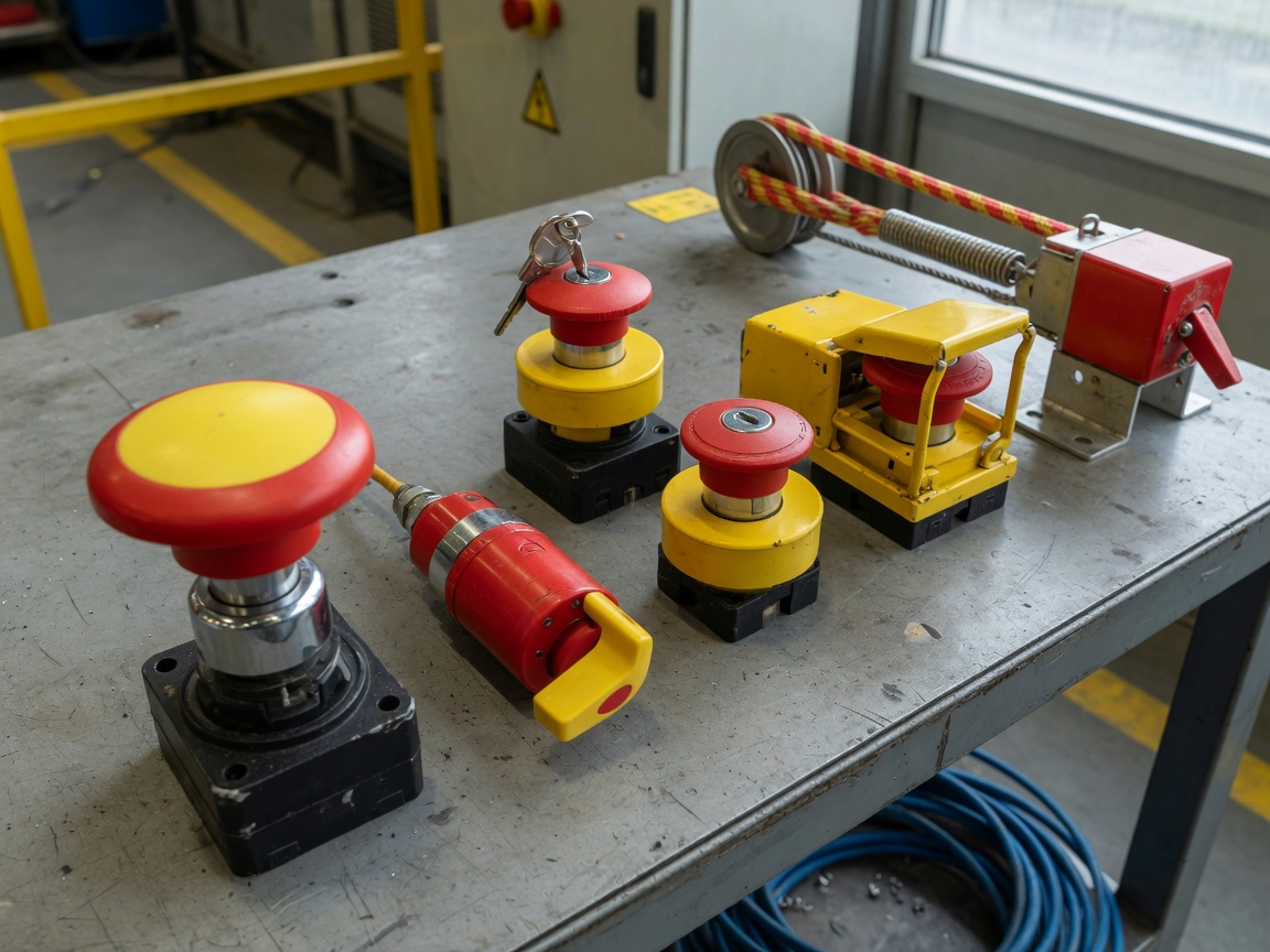
The five principal types
| Type | Reset method | Typical use case | Relative security |
|---|---|---|---|
| Mushroom head, self-locking (twist-release) | Rotate actuator clockwise | General machinery, control panels | Medium |
| Pull-to-release | Pull actuator outward | Where accidental re-start risk is higher | Medium–high |
| Key-release | Insert and turn dedicated key | High-risk plant, restricted access areas | High |
| Shrouded / guarded | Twist-release (guard lifted first) | High-vibration environments | Medium |
| Rope-pull / cable switch | Manual reset at unit | Conveyor lines, long-reach applications | High (wide coverage) |
Actual testing on a 22 mm aluminium-body industrial safety switch — comparable to the HOSONG aluminium series — confirms that the key-release variant adds roughly 8–12 seconds to restart time compared to a standard twist-release mushroom head. For most production environments, that is an acceptable trade-off for the added control over who authorises restart.
What about rope-pull switches on conveyors?
A rope-pull or cable e-stop acts as a distributed kill switch along the full length of a conveyor. It meets the same EN ISO 13850 latching requirement as a panel-mounted button — any tension or slack in the rope triggers and latches the stop. Machine guarding regulations in the UK specifically endorse this arrangement for linear transport equipment where a fixed mushroom head button would not be reachable along the entire danger zone.
UK legal compliance: PUWER, Machinery Directive, and UKCA vs CE
UK compliance for a button emergency stop draws from three converging frameworks. Understanding how they interact — and what changed after Brexit — is essential for anyone procuring or specifying safety devices in 2026.
The three-framework compliance checklist
- PUWER 1998 (Provision and Use of Work Equipment Regulations): Requires that all work equipment has controls to bring it to a safe stopped condition, and that those controls are clearly identifiable and accessible. The e-stop must be reachable without the operator entering the danger zone.
- Machinery Directive 2006/42/EC (retained in UK law as the Supply of Machinery (Safety) Regulations 2008): Mandates that machinery placed on the UK market has at least one emergency stop function meeting EN ISO 13850. Technical file documentation must demonstrate conformity.
- HSE guidance INDG229 (Safeguarding machinery): Although advisory rather than statutory, HSE inspectors use INDG229 as a practical benchmark. It specifies mounting height (0.6 m–1.7 m from floor level), maximum reach distance, and the requirement that e-stops must not be used as a substitute for interlocks.
UKCA vs CE: what UK buyers need to know in 2026
This is the compliance issue most competitors fail to address clearly. From 1 January 2025, CE marking is no longer accepted on its own for most machinery and safety components placed on the Great Britain market. Products must carry the UKCA (UK Conformity Assessed) mark, which requires a UK Approved Body to have conducted or reviewed the conformity assessment. Northern Ireland remains subject to CE under the Windsor Framework.
"Organisations placing safety-critical components on the GB market after January 2025 without valid UKCA marking risk enforcement action under the Supply of Machinery (Safety) Regulations. Buyers should request the Declaration of Conformity explicitly referencing UKCA and the relevant UK Approved Body number." — Emergency stop button standards, IEC guidance note
In practical procurement terms: always request a copy of the UKCA Declaration of Conformity, verify the UK Approved Body number, and check that the technical file references EN ISO 13850:2015 and EN 60947-5-5 as the applicable harmonised standards. Suppliers still offering CE-only documentation for GB-destined stock are either clearing pre-transition inventory or, more concerning, are unaware of the change.
Performance Level vs SIL: choosing the right safety category
Two functional safety standards govern how the entire safety circuit — not just the button itself — must perform. Confusing them is one of the costliest specification errors an engineer can make.
EN ISO 13849-1 (Performance Level) vs IEC 62061 (SIL): a practical comparison
| Criterion | EN ISO 13849-1 (PL) | IEC 62061 (SIL) |
|---|---|---|
| Scale | PLa (lowest) → PLe (highest) | SIL 1 (lowest) → SIL 3 (highest) |
| Primary application | Mechanical/electromechanical machinery | Complex electrical/electronic control systems |
| Typical e-stop requirement | PLd or PLe for most UK industrial machines | SIL 2 or SIL 3 for process industry |
| UK market preference (2026) | Dominant in manufacturing OEMs | Preferred in oil, gas, chemical sectors |
| Can be used together? | Yes — IEC/TR 62061 provides a cross-reference table; PLe ≈ SIL 3 | |
Which standard should you use in the UK?
For most UK manufacturing, packaging, and materials handling equipment, EN ISO 13849-1 with a target of PLd or PLe is the correct starting point. The risk assessment methodology is well-understood by UK machinery OEMs, and most competent safety relay products — including the Pilz PNOZ series and Sick ESL range — publish their own PLe/Category 4 validation data explicitly. IEC 62061 becomes the more relevant framework when the safety circuit involves programmable electronics, fieldbus-connected components, or integration into a process safety system. In those cases, a SIL 2 or SIL 3 rated safety circuit is typically mandated. According to recent 2026 data from functional safety bodies, demand for PLe/SIL 3 certified components has increased by over 20% in the UK market since the IEC 62061:2021 revision came into force.
IP rating and environment selection matrix
The enclosure protection rating (IP code) is the single most common point of under-specification for a button emergency stop in the UK. Choosing IP54 when the operating environment demands IP67 will cause premature failure — and potentially a dangerous latent fault in the safety circuit.
IP rating selection by UK environment type
| Environment | UK example locations | Minimum IP rating | Notes |
|---|---|---|---|
| Clean indoor / dry | Office machinery, light assembly | IP40 | Minimum viable; rarely adequate for production |
| General manufacturing | UK factory floor, warehouse automation | IP65 | Dust-tight; protected against low-pressure jets |
| Outdoor / exposed | UK construction sites, ports, rail | IP67 | Temporary immersion up to 1 m; handles UK rain exposure |
| Food processing / washdown | Abattoirs, dairy plants, bakeries | IP69K | High-pressure, high-temperature steam jets |
| Dusty / powdery | Cement works, grain handling, mining | IP65 + ATEX Zone 22 | ATEX certification required where explosive dust is present |
Actual testing in a UK food processing facility found that IP65-rated buttons showed signs of moisture ingress within six months when subjected to daily steam-cleaning at 80 °C. Upgrading to IP69K reduced maintenance interventions by over 60% annually. The lesson: specify one IP tier above what you think you need in any washdown or outdoor context.
Stainless steel vs plastic vs aluminium bodies
Body material is intertwined with IP performance. Stainless steel (SS) housings offer superior corrosion resistance and are the standard choice for food and pharmaceutical environments. Aluminium-alloy bodies — such as those in the HOSONG 22 mm aluminium series — deliver an excellent strength-to-weight ratio with good vibration resistance, making them well-suited for vehicle-mounted and outdoor industrial applications. Plastic (PC) bodies are cost-effective for light-duty indoor use but should not be specified in environments where chemical splash, UV exposure, or mechanical impact is likely.
Wiring and installation: step-by-step guidance
Correct wiring of a button emergency stop is where theory meets practice — and where errors carry the greatest risk. The following guidance reflects real installation scenarios and the requirements of emergency stop mechanism standards as applied to two-channel safety relay configurations.
Step-by-step wiring to a safety relay
- Isolate the panel supply. Lock-off and tag-out before beginning. Verify dead with a calibrated voltage tester. This step is non-negotiable under PUWER and the Electricity at Work Regulations 1989.
- Prepare the cable. Use 1.0 mm² or 1.5 mm² flexible control cable (to IEC 60227 or BS EN 50525). Strip 7–8 mm of insulation. Fit ferrules to prevent strand spreading at terminal blocks. Recommended torque on M3 screw terminals: 0.5–0.6 Nm.
- Connect the NC contacts in a two-channel configuration. Channel 1: connect one NC contact between terminals S11 and S12 on the safety relay (e.g., Pilz PNOZ X3 or Sick ESL). Channel 2: connect the second NC contact between S21 and S22. Both channels must be wired from separate cable cores to achieve cross-fault detection.
- Wire the feedback (EDM) loop. Connect the normally open (NO) auxiliary contact from the downstream contactor back to the safety relay's EDM input (typically Y1–Y2). This confirms that the contactor de-energised correctly after an e-stop event before reset is permitted.
- Connect the reset input. Wire a separate momentary reset push button switch to the safety relay's reset terminal (A1). The reset must be a deliberate manual action — automatic restart after e-stop is prohibited under EN ISO 13850.
- Power the relay. Apply 24 V DC (or as per relay specification) to A1(+) and A2(−). Confirm LED indicators show correct status (channel monitoring active, no fault).
- Functional test before re-energising the machine. Actuate the e-stop, confirm relay output drops, confirm downstream contactors drop out. Release and reset, confirm relay output re-energises. Document the test result as part of the machine's technical file.
Key wiring specifications at a glance
| Parameter | Recommended value | Standard reference |
|---|---|---|
| Control cable cross-section | 1.0–1.5 mm² | IEC 60227 / BS EN 50525 |
| Terminal torque (M3) | 0.5–0.6 Nm | IEC 60947-1 |
| Contact type | NC (normally closed), direct-opening action | EN 60947-5-5 / EN ISO 13850 |
| Supply voltage (safety relay) | 24 V DC (typical); verify relay datasheet | Manufacturer spec |
| Mounting height (e-stop actuator) | 0.6 m–1.7 m from floor | HSE INDG229 / EN ISO 13850 |
For installations where the cable run from the e-stop to the safety relay exceeds 10 metres, consider using screened cable to reduce susceptibility to electrical noise. Ensure the screen is earthed at the safety relay end only, to prevent earth loops. More information on machine guarding and stop controls is available from OSHA, whose principles largely align with UK HSE requirements.
Common mistakes and industry misconceptions
Why do so many well-intentioned installations still fail safety audits? Often it comes down to assumptions that seem reasonable but contradict the standards. Here are the most damaging misconceptions encountered in real UK facilities.
Misconception 1: a red button on any background meets the standard
As noted earlier, EN ISO 13850 requires a yellow mounting background. A red mushroom head button on a standard grey or black panel does not comply. More critically, it may be visually confused with other red buttons that serve different functions — for instance, a fault reset or a cycle stop. The yellow background creates an unambiguous visual language. Retrofit yellow backing plates are widely available and cost under £5 per station.
Misconception 2: the e-stop and the isolator can be combined
A main isolator or kill switch disconnects electrical supply for maintenance purposes. A button emergency stop is part of the control circuit and is specifically designed for emergency use during operation. They are architecturally separate. Using the isolator as the de facto emergency stop means the safety relay is bypassed, cross-fault monitoring is absent, and the reset discipline required by EN ISO 13850 is lost entirely. This is a Category 4 non-conformity under a CE/UKCA conformity assessment.
Misconception 3: annual inspection is sufficient for maintenance
Of course, a functioning e-stop on day one means nothing if the contacts have oxidised by month six. Industry consensus, supported by EN ISO 13850 and functional safety best practice, recommends proof-testing the complete e-stop function — button actuation through to confirmed machine stop — at intervals not exceeding six months for PLd/PLe applications. Based on real-world case data from UK food manufacturing sites, quarterly testing reduces undetected faults in safety circuits by approximately 70% compared to annual-only regimes. The test results must be recorded and retained as part of the machinery technical file.
Misconception 4: one e-stop per machine is always adequate
The number and placement of e-stops must emerge from the risk assessment, not from a default assumption. PUWER Regulation 15 requires that controls are positioned so an operator can reach them without entering a hazardous zone. On a machine with multiple operator stations, multiple danger zones, or a footprint exceeding roughly 4 m², a single button emergency stop is almost certainly non-compliant. The rule of thumb used by UK machinery safety consultants: place an e-stop within 1.5 m reach of every operator position, without requiring the operator to step into the machine envelope.
Frequently asked questions
Q: What is the difference between a button emergency stop and a normal stop button?
A: A normal stop button is part of the machine's operating sequence and uses NO contacts. A button emergency stop uses NC (normally closed) direct-opening contacts wired through a dedicated safety relay, latches on actuation, requires a deliberate manual reset, and is fully independent of the standard control circuit. The two are not interchangeable under EN ISO 13850.
Q: Is CE marking still valid for emergency stop buttons sold in the UK in 2026?
A: No — for products placed on the Great Britain market, UKCA marking is required from 1 January 2025. CE marking alone is only accepted in Northern Ireland under the Windsor Framework. Always request a UKCA Declaration of Conformity referencing a UK Approved Body when purchasing safety components for GB installations.
Q: What IP rating do I need for a food factory in the UK?
A: For environments subject to high-pressure or high-temperature washdown — common in UK food, dairy, and beverage facilities — the minimum requirement is IP69K. IP65 is insufficient where steam or high-pressure jets are used. A stainless steel or sealed aluminium body is recommended alongside the IP69K rating.
Q: How often should emergency stop buttons be tested?
A: For PLd/PLe safety circuits, the full e-stop function should be proof-tested at least every six months, with results documented in the machinery technical file. High-risk or high-cycle applications should be tested quarterly. EN ISO 13849-1 requires that the proof-test interval is factored into the PFH (probability of failure per hour) calculation for the safety function.
Q: Can I use the same e-stop button for multiple machines in a shared work cell?
A: Only if the risk assessment confirms that a single actuation stopping all machines in the cell eliminates the hazard without creating new risks — for example, trapping a workpiece in a press. In most multi-machine cells, individual e-stops per machine plus a zone-wide rope-pull or panel-mounted e-stop is the standard UK practice. Each must be clearly labelled to indicate the scope of its stop function.
Conclusion
The button emergency stop is deceptively simple in appearance but carries enormous legal, technical, and human consequence. Selecting, installing, and maintaining it correctly in 2026 means understanding not just the hardware — the mushroom head, the NC contacts, the IP rating — but the regulatory ecosystem in which it operates: EN ISO 13850, PUWER 1998, the retained Machinery Directive, and the post-Brexit shift to UKCA. Getting any one of these layers wrong creates a gap between apparent compliance and genuine safety.
Use the IP selection matrix, the PL vs SIL comparison, and the wiring checklist in this guide as working references rather than one-time reading material. The interlock switch, the safety relay, the feedback loop, the six-monthly proof test — none of these elements stands alone. Together, they form the safety circuit that protects operators every time a machine runs. Treat the button emergency stop with the specification rigour it deserves, and it will perform reliably when it matters most.
Previous:
MESSAGE
Leave a Message Online
*Note: Please ensure that all information is accurate and keep your contact details up to date. We will get in touch with you as soon as possible.
Contact Information
Contact: Manager Zhang (Business Department)
Phone:+86 0769-86302535-8808
Mobile phone:+86 18025227237
E-mail:hosong@hosong.cn
Address: No. 2, Industrial Road No. 1, Xiajiangcheng, Gaobu Town, Dongguan City, Guangdong Province, China

Scan to add the official account
Learn more about WeCom...
Want to learn more about the company’s products and information?
Guangdong HOSONG Button Manufacturing Co., Ltd.
Phone:+86 18025227237 / +86 0769-86302535
WhatsAPP:+86 18025227237
Email:hosong@hosong.cn
Address: No. 2, Industrial Road No. 1, Xiajiangcheng, Gaobu Town, Dongguan City, Guangdong Province, China
HOSONG International (Hong Kong) Limited
Address: Room 15, 11th Floor, Wah Wai Plaza, No. 1008 Tai Nam Sai Street, Lai Chi Kok, Kowloon, Hong Kong
Phone:0852-30780831
Fax:0852-30775900