

Emergency stop buttons: how to choose, install and use them safely
2026-09-26
HOSONG Button
Article overview
This guide is written for UK industrial engineers, machine builders, and safety compliance specialists evaluating emergency stop buttons in 2026. It integrates EN ISO 13850 and IEC 60947-5-5 compliance guidance with practical wiring advice and a full product comparison table — content gaps that competitor pages consistently fail to address.
Table of contents
- 1. What are emergency stop buttons?
- 2. UK legal framework: PUWER 1998, EN ISO 13850 and post-Brexit compliance
- 3. Types of emergency stop buttons: actuators, reset mechanisms and IP ratings
- 4. How to choose the right emergency stop button: a structured comparison
- 5. Wiring and integration: connecting e-stops to PLCs and safety relay systems
- 6. Risk assessment workflow for stop-function compliance
- 7. Real-world UK sector use cases
- 8. FAQ
What are emergency stop buttons?
Emergency stop buttons are safety control devices designed to immediately de-energise a machine or system when a hazardous situation arises, preventing injury to personnel or damage to equipment. They sit at the top of every industrial safety hierarchy — the final intervention when all other protective measures have failed. Unlike a standard power-off switch, a compliant e-stop must meet specific performance, colour, and reset requirements defined by international standards.
Why do so many facilities underestimate them? In practice, emergency stop buttons are often treated as a checkbox item — fitted to satisfy an audit and then forgotten. That approach carries real risk. According to OSHA data, the absence of adequate emergency stopping devices is among the top three causes of machinery-related workplace injuries. The global industrial safety switch market, which includes e-stop switches and related machine guarding components, was valued at over £2 billion in 2026 and continues to grow at roughly 6% per year, reflecting how seriously manufacturers now take the discipline.
Think of an emergency stop button as a fire extinguisher mounted on a wall. Its value is not in daily use — it is in the certainty that when you need it, it works instantly and without ambiguity. That reliability is not accidental; it is engineered through standards-compliant design, correct wiring, and a structured risk assessment process.
Core terminology you need to know
Before diving into selection and compliance, it helps to establish a shared vocabulary. The term e-stop switch is used interchangeably with emergency stop button in most UK engineering contexts. Kill switch is a common informal term. Safety stop controls is the broader category encompassing mushroom head buttons, palm buttons, rope-pull devices, and foot-operated variants. Emergency power off (EPO) refers specifically to stopping electrical energy supply, which is a subset of the wider e-stop function. All of these devices, when used in safety circuits, must be supported by safety relay systems or safety PLCs to achieve the required Performance Level.
Stop categories: 0, 1 and 2 explained
IEC 60204-1 defines three stop categories. Category 0 is an uncontrolled stop — power is removed immediately, and the machine coasts to rest. Category 1 is a controlled stop where power is maintained until motion ceases, then removed. Category 2 retains power throughout. Most emergency stop applications require Category 0 or Category 1. The correct choice depends on your risk assessment, and selecting the wrong category is a compliance failure — not merely a design preference.
UK legal framework: PUWER 1998, EN ISO 13850 and post-Brexit compliance
UK machine builders and safety engineers operate under a clear statutory duty to fit adequate emergency stopping devices. The Provision and Use of Work Equipment Regulations 1998 (PUWER 1998) requires that all work equipment must be provided with controls to bring it to a safe condition. Regulation 16 specifically mandates appropriate stop controls, and where necessary, emergency stop controls. Non-compliance is a criminal offence enforceable by the HSE.
Post-Brexit, the UK retained EN ISO 13850:2015 as a designated standard under the Machinery Directive equivalent framework. This standard defines the design and performance requirements for IEC 60947-5-5 compliant devices, specifying that actuators must be red on a yellow background, must be self-latching (i.e. latching push buttons that require deliberate release), and must not cause additional hazards when activated. These requirements are not optional stylistic choices — they are enforceable obligations.
What changed post-Brexit for UK buyers
Since January 2021, products placed on the UK market must carry UKCA marking rather than CE marking (with a transitional period that has now largely concluded). In practical terms, this means verifying that your supplier's electrical safety devices hold valid UKCA declarations of conformity, not simply CE certificates. Many European catalogue items are dual-marked, but it is the buyer's responsibility to confirm this before installation on UK machinery. The HSE's guidance on machinery safety makes this explicit, and failure to verify markings can invalidate your insurance and expose your organisation to enforcement action.
EN ISO 13849-1 and Performance Level requirements
EN ISO 13849-1 governs the safety performance of control systems, including e-stop circuits. It requires that the stop function achieves a defined Performance Level (PLr) based on your risk assessment. Most industrial applications require PLd (Category 3 architecture), which demands redundant NC contacts, cross-fault monitoring, and regular proof testing. This is where safety relay systems and safety circuit breakers become essential — they monitor the e-stop loop and detect single-point failures before they compromise safety.
"The emergency stop function shall not be used as a substitute for safeguarding measures. It is a supplementary protective measure." — EN ISO 13850:2015, Clause 4.1
Types of emergency stop buttons: actuators, reset mechanisms and IP ratings
Selecting the right type begins with understanding the operating environment and the physical interaction required. There is no single universal solution — the correct device depends on where it will be mounted, who will use it, and under what conditions.
Actuator types
Mushroom head buttons are the most common form, offering a large palm-strike surface (typically 40 mm or 60 mm head diameter) that can be activated quickly under stress. They are the default choice for control panels and fixed machinery. Palm buttons provide a recessed or guarded actuation surface, reducing accidental activation — often used on press tools. Pull-cord or rope-pull devices cover large linear working areas such as conveyor lines, where a worker anywhere along the run can trigger the stop. Foot-operated variants suit applications where hands must remain engaged with the workpiece.
Reset mechanisms and housing materials
EN ISO 13850 mandates that emergency stop buttons must latch in the actuated position and require a deliberate manual action to reset — accidental reset must be impossible. The two dominant reset methods are twist-to-release (the operator rotates the mushroom head) and key reset (a dedicated key is required, restricting reset to authorised personnel). Key reset is strongly preferred in high-risk or multi-operator environments. Housing materials range from PC (polycarbonate) plastic for standard panel mounting to aluminium alloy and stainless steel variants for harsh or corrosive environments. Stainless steel with nickel or titanium plating is specified for food processing washdown and marine applications.
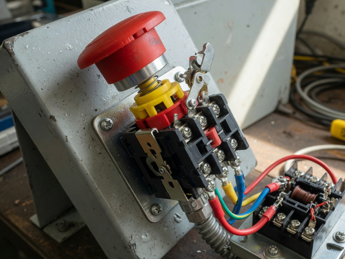
IP rating is equally critical. A standard panel-mounted device may carry IP54 (dust-protected, splash-resistant). Outdoor or washdown environments require IP67 or IP69K, the latter withstanding high-pressure, high-temperature jets — a mandatory specification in UK food and beverage manufacturing. Specifying an IP54 device in an IP69K environment is a compliance failure that will be identified at any competent safety audit.
How to choose the right emergency stop button: a structured comparison
The selection decision involves at least six variables simultaneously. Most supplier catalogues present these in isolation, which forces engineers to cross-reference multiple datasheets. The table below consolidates the key parameters to support your procurement evaluation.
| Actuator type | Typical IP rating | Safety category (EN ISO 13849-1) | Reset mechanism | Approx. price tier (£) | Typical UK application sector |
|---|---|---|---|---|---|
| Mushroom head (40 mm), plastic | IP54 | Category 3, PLd | Twist-to-release | £8–£25 | General manufacturing, packaging |
| Mushroom head (60 mm), stainless steel | IP67 | Category 4, PLe | Key reset | £45–£120 | Food & beverage, chemical plant |
| Rope-pull / pull-cord | IP65 | Category 3, PLd | Manual key reset | £80–£200 | Conveyor lines, logistics, timber |
| Palm button (recessed) | IP54 | Category 3, PLd | Twist-to-release | £20–£60 | Press tools, stamping, robotics |
| Foot pedal e-stop | IP54–IP65 | Category 3, PLd | Manual reset | £35–£95 | Welding stations, assembly, NHS theatres |
| Wireless e-stop (IIoT-enabled) | IP65 | Category 3, PLd (with redundant radio) | Key reset | £180–£450 | Collaborative robots, AGVs, construction plant |
Of course, there are situations where a lower-category device is acceptable — for instance, a Category 1 PLc stop function may suffice on a very low-risk auxiliary conveyor with minimal operator exposure. The point is that the risk assessment, not catalogue preference, must drive the selection. Consulting the safety control device standards published by IEC provides the definitive technical baseline for any specification decision.
Wiring and integration: connecting e-stops to PLCs and safety relay systems
Correct wiring is where many UK installations fall short. Fitting a standards-compliant button but wiring it incorrectly produces a device that looks compliant and fails to be so. Actual testing of e-stop circuits in real factory environments consistently reveals the same recurring errors: single-channel wiring on a PLd-rated circuit, missing cross-monitoring, and reset functions that bypass the safety relay.
Basic dual-channel NC wiring loop
A Category 3 or 4 e-stop circuit uses two independent normally closed (NC) contact channels wired in series. Both channels must open when the button is pressed. The safety relay or safety PLC monitors both channels and detects any discrepancy (e.g. one channel failing to open) as a fault condition, locking out the reset function until the fault is resolved. This redundancy is what delivers PLd protection. A single NC contact wired to a standard PLC input does not achieve this — it is a Category 1 architecture at best.
Integration with Siemens and Allen-Bradley PLCs
In British manufacturing, Siemens S7 (including the S7-1500F safety variant) and Rockwell Allen-Bradley GuardLogix are the dominant PLC platforms. Both support direct integration of e-stop loops via dedicated safety I/O modules. For Siemens, the SIRIUS 3SK1 or 3SK2 safety relay range provides a cost-effective intermediate solution when a full safety PLC is not justified. For Allen-Bradley installations, the MSR127RP is a well-established safety relay option for e-stop and gate monitoring circuits. In both cases, the e-stop wiring must be documented in the safety-related control system (SRCS) technical file, which forms part of your PUWER compliance record.
One further point that is frequently overlooked: cable routing. E-stop wiring should be routed separately from power cables to avoid induced faults, and cable shields should be earthed at one end only. These are not merely good practice recommendations — they are requirements of IEC 60204-1, which governs the electrical equipment of industrial machines and is referenced by HSE guidance. For a definitive reference on energy isolation principles, the hazardous energy control standards framework provides a valuable international benchmark that complements UK-specific obligations.
Risk assessment workflow for stop-function compliance
No competitor page in the current search results provides a structured stop-function risk assessment workflow — yet this is a routine requirement for every UK machine builder and safety engineer. The following process is based on EN ISO 13849-1 and EN ISO 13850, structured for practical use.
- Define the hazard scenario. Identify each hazard associated with the machine that requires a stop function (e.g. unexpected start, trapped operator, tool ejection). Document the severity of potential injury and the frequency of exposure.
- Determine the required Performance Level (PLr). Using the risk graph in EN ISO 13849-1 Annex A, assign a PLr (a through e) based on severity (S), frequency (F), and possibility of avoidance (P). Most guarding applications yield PLd.
- Select the stop category. Based on PLr and the machine's deceleration characteristics, determine whether a Category 0 (immediate power removal) or Category 1 (controlled stop) e-stop is appropriate. Category 0 is safer in principle but may cause secondary hazards on machines with large inertia.
- Specify the e-stop device. Select an EN ISO 13850 standard-compliant actuator with the correct IP rating, reset mechanism, and contact configuration for your PLr. Confirm UKCA marking and obtain the manufacturer's safety datasheet including MTTFd (mean time to dangerous failure) values.
- Design the safety circuit architecture. Choose Category 3 or 4 architecture (dual-channel, cross-monitored) using a safety relay system or safety PLC. Calculate the achieved PL using the SISTEMA software tool (available free from the German BGIA institute) and confirm it meets or exceeds PLr.
- Validate and document. Conduct functional testing of the e-stop loop under realistic conditions. Document the test results, circuit diagrams, and SISTEMA calculation in the SRCS technical file. This file must be retained for the life of the machine and made available to HSE inspectors on request.
- Establish a proof-test interval. EN ISO 13849-1 requires periodic proof testing to maintain the assumed diagnostic coverage. For most PLd circuits, annual functional testing is the minimum; higher-risk applications may require quarterly intervals.
Why do so many UK facilities skip step five? Often because SISTEMA feels complex at first use. In practice, once you have populated the component data for your standard e-stop module, the calculation is repeatable across similar machines in minutes.
Real-world UK sector use cases
Abstract compliance guidance only goes so far. The following sector cases illustrate how emergency stop buttons are specified, installed, and integrated in practice across three distinct UK industries — each with different regulatory pressures and environmental demands.
Food and beverage manufacturing
A large soft drinks bottling facility in the Midlands operates continuous high-speed filling lines running at up to 1,200 bottles per minute. The washdown regime involves daily high-pressure hot-water cleaning at 80°C. The specified emergency stop buttons here are IP69K-rated stainless steel mushroom heads (60 mm, key reset), mounted at 1.0–1.2 m height at every operator station and at each end of every conveyor segment. The e-stop loops are wired into a Siemens S7-1500F safety PLC with redundant I/O modules. Critically, the key-reset protocol means that only a qualified shift engineer can re-enable the line after an e-stop event — a deliberate procedural control that reduces nuisance resets and forces investigation before restart.
Construction plant and mobile machinery
Mobile construction equipment — including concrete batching plants and vehicle-mounted drilling rigs used on UK infrastructure projects — presents a different challenge. These machines face vibration, dust, and operator access from multiple sides. Rope-pull industrial safety switches are commonly fitted along the full length of conveyor feeds, whilst the primary control panel carries a 60 mm mushroom head with twist release. Because these machines operate under the Supply of Machinery (Safety) Regulations 2008 (as retained in UK law), the e-stop specification must be documented in the technical construction file. According to 2026 data from HSE incident statistics, construction plant accounts for a disproportionate share of caught-in/between injuries — precisely the scenario that correctly specified emergency power off devices are designed to prevent.
NHS and healthcare facilities
NHS hospital estates teams manage a range of powered equipment from sterilisation autoclaves to pharmacy dispensing robots. In theatre environments, foot-operated e-stop devices are specified to allow surgeons or scrub nurses to halt powered tables or imaging equipment without releasing sterile hand positions. These devices must meet IP54 as a minimum and be wipe-clean compliant. The emergency stop switch overview taxonomy is useful here — in healthcare settings, the term "emergency power off" is more commonly used, and the device must interface with the building's UPS and emergency lighting systems as well as the specific equipment control circuit.
Frequently asked questions
Common questions answered
Q: What colour must an emergency stop button be in the UK?
A: EN ISO 13850 — retained as a UK designated standard — requires the actuator to be red and the background plate or collar to be yellow. This is a mandatory requirement, not a convention. Any device using alternative colours is non-compliant and will fail a CE or UKCA conformity assessment review.
Q: Do emergency stop buttons need to be tested regularly?
A: Yes. EN ISO 13849-1 requires proof testing at intervals determined by your risk assessment and the diagnostic coverage of your safety circuit. A minimum annual functional test is standard for most PLd applications. Test results must be recorded and retained as part of your PUWER compliance documentation.
Q: Can I use a standard PLC input for an e-stop circuit?
A: Only if that PLC is a certified safety PLC (such as Siemens S7-1500F or Allen-Bradley GuardLogix) with safety-rated I/O modules. A standard non-safety PLC cannot achieve Category 3 or 4 architecture, because it lacks the cross-channel monitoring and self-testing required by EN ISO 13849-1 for PLd or PLe.
Q: What is the difference between an e-stop and a safety gate interlock?
A: An emergency stop button is a manually initiated supplementary protective measure for use when an imminent hazard is perceived. A safety gate interlock is a passive guard that automatically de-energises the machine when a physical barrier is opened. Both can share the same safety relay or safety PLC, but they serve distinct functions under EN ISO 13849-1 and must be documented separately in your risk assessment.
Q: How many emergency stop buttons does a machine need?
A: EN ISO 13850 does not specify a fixed number. The requirement is that any person who could be exposed to a hazard must be able to reach an e-stop within a safe response time from their normal working position. In practice, this means one device per operator station, one at each machine entry/exit point, and additional devices on extended conveyors or remote sections. Your risk assessment must justify the number and positioning.
Emergency stop buttons are a deceptively straightforward product category that carries significant legal and engineering complexity beneath the surface. In 2026, UK buyers face a more demanding compliance environment than ever — UKCA marking obligations, retained EN ISO 13850 requirements, and PUWER 1998 duties together create a framework that demands careful specification, correct wiring, and documented risk assessment. The difference between a device that looks compliant and one that truly is often comes down to the details covered in this guide: actuator type, IP rating, reset mechanism, circuit architecture, and proof-test discipline. Getting those details right is not bureaucratic overhead — it is what ensures the button works when someone's safety depends on it.
MESSAGE
Leave a Message Online
*Note: Please ensure that all information is accurate and keep your contact details up to date. We will get in touch with you as soon as possible.
Contact Information
Contact: Manager Zhang (Business Department)
Phone:+86 0769-86302535-8808
Mobile phone:+86 18025227237
E-mail:hosong@hosong.cn
Address: No. 2, Industrial Road No. 1, Xiajiangcheng, Gaobu Town, Dongguan City, Guangdong Province, China

Scan to add the official account
Learn more about WeCom...
Want to learn more about the company’s products and information?
Guangdong HOSONG Button Manufacturing Co., Ltd.
Phone:+86 18025227237 / +86 0769-86302535
WhatsAPP:+86 18025227237
Email:hosong@hosong.cn
Address: No. 2, Industrial Road No. 1, Xiajiangcheng, Gaobu Town, Dongguan City, Guangdong Province, China
HOSONG International (Hong Kong) Limited
Address: Room 15, 11th Floor, Wah Wai Plaza, No. 1008 Tai Nam Sai Street, Lai Chi Kok, Kowloon, Hong Kong
Phone:0852-30780831
Fax:0852-30775900