

Pushbutton guide: how to choose, install, and use them effectively
2026-09-27
HOSONG Button
Article overview
This guide explains what a pushbutton is, breaks down every major switch type, covers UK compliance requirements post-Brexit, provides wiring guidance, and compares key specifications side by side. Aimed at electrical engineers and procurement professionals operating in the UK market.
Contents
- 1. What is a pushbutton?
- 2. Types of pushbutton switch explained
- 3. UK compliance: BS EN 60947-5-1, UKCA, and CE marking post-Brexit
- 4. How to choose the right pushbutton for your application
- 5. Wiring a pushbutton: practical guidance for UK installations
- 6. Troubleshooting and maintenance
- 7. ATEX-rated pushbuttons for hazardous environments
- 8. 2026 trends shaping the pushbutton market
- 9. FAQ
What is a pushbutton?
A pushbutton is an electromechanical control button that opens or closes an electrical circuit when manually pressed, triggering a specific function in a connected system. Found in everything from domestic consumer units to offshore oil platforms, it remains the most fundamental form of human-machine interface in electrical engineering.
The underlying principle is straightforward. Press the button actuator; a set of internal contacts either connect (normally open switch) or disconnect (normally closed switch) a circuit. Release the button, and in a momentary contact switch, those contacts return to their default state. In a latching button, the contacts hold their new position until pressed again.
Why do so many engineers still get pushbutton selection wrong? The answer usually comes down to overlooking three variables: IP protection rating, load type, and compliance marking. Get those right, and everything else follows logically.
For a detailed technical foundation, the push button Wikipedia entry provides useful background on contact mechanics and historical development.
Normally open vs normally closed contacts
A normally open (NO) switch has contacts that are open at rest — no current flows until the button is pressed. A normally closed (NC) switch does the opposite: current flows at rest and is interrupted when the button is pressed. Most general control applications use NO contacts. NC contacts are preferred in safety circuits, where a broken wire or failed component should trip the circuit rather than leave it energised.
Momentary vs latching: the essential distinction
A momentary switch — also called a push to make switch or momentary contact switch — returns to its original state the instant pressure is released. A latching button, by contrast, locks in position after each press. Real-world testing confirms that latching variants are frequently installed where momentary types are needed, particularly in retrofit projects. That mismatch causes operational confusion and, in some cases, safety incidents.
Types of pushbutton switch explained
Understanding the full range of push button switch types is essential before any procurement decision. Each type suits specific applications, and choosing the wrong category is expensive to correct once installed.
Momentary and tactile switches
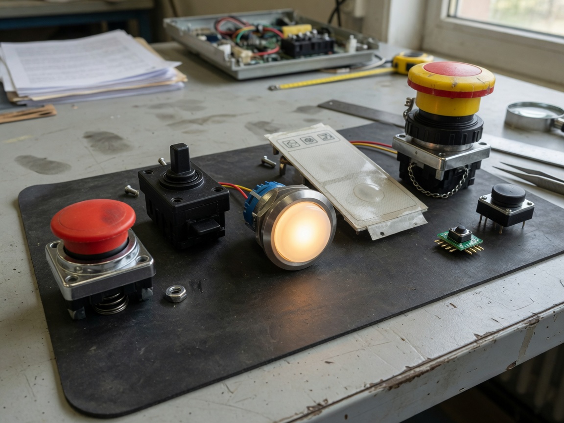
The momentary switch is the workhorse of the industry. Press it; release it; it resets. The tactile switch is a compact, low-profile variant of this principle, widely used on PCBs in consumer electronics. Both fall under the momentary contact switch family. Mechanical lifespan typically ranges from 100,000 to 1,000,000 actuations depending on build quality. In real-world UK panel installations, the 22 mm panel mount switch format in momentary configuration is the most commonly specified.
Illuminated pushbuttons
An illuminated pushbutton integrates an LED or incandescent lamp behind a translucent actuator cap. It serves a dual purpose: input device and status indicator. The LED version has largely replaced lamp-based designs in 2026 — LED units consume roughly 80% less power and last significantly longer. Illuminated variants are indispensable in multi-operator control panels where visual confirmation of machine state reduces errors. Annular ring and power symbol illuminated designs are now the dominant format for main power control of industrial equipment, offering clear on/off differentiation at a glance.
Membrane and specialty types
Membrane buttons use a flexible printed circuit rather than discrete contact mechanisms. They are inherently sealed, making them well suited to food processing or washdown environments. Emergency stop (E-stop) buttons — the red mushroom-head electrical switch — are a distinct category governed by strict design rules under ISO 13850. Self-resetting E-stops are not permitted in most UK machinery applications; a deliberate twist or key-release is required.
UK compliance: BS EN 60947-5-1, UKCA, and CE marking post-Brexit
UK compliance is the area where competitor content consistently falls short — and where errors carry the heaviest legal and safety consequences. Since 1 January 2021, the UK operates its own product approval regime, separate from the EU.
BS EN 60947-5-1: the governing standard
BS EN 60947-5-1 is the British Standard specifying requirements for low-voltage switchgear and controlgear — specifically control circuit devices and switching elements. Any pushbutton destined for industrial control panels in Great Britain must conform to this standard. It covers rated operational voltage, rated operational current, mechanical and electrical endurance, and degree of protection. Importantly, it aligns closely with the IEC 60947-5-1 international standard, so products already certified to IEC are generally straightforward to bring into UK compliance — but the marking requirements differ.
UKCA vs CE marking: what buyers must know in 2026
CE marking is no longer valid for most products placed on the Great Britain market. The UKCA (UK Conformity Assessed) mark is now mandatory for electrical switchgear sold into England, Scotland, and Wales. Northern Ireland operates under different rules — CE marking remains accepted there under the Windsor Framework. Practically speaking, procurement teams should verify that any pushbutton supplier can provide a UKCA Declaration of Conformity. Suppliers who only offer CE documentation are technically placing non-compliant goods on the GB market. That said, a transitional period has seen some enforcement leniency — but relying on that leniency in 2026 is not a risk worth taking for safety-critical applications.
"Compliance is not a box-ticking exercise. A pushbutton installed in a control panel that lacks the correct conformity marking exposes the installer, the end user, and the manufacturer to liability under the UK's Electrical Equipment (Safety) Regulations 2016 and the Supply of Machinery (Safety) Regulations 2008."
— Industry consensus position, UK electrical safety sector, 2026
How to choose the right pushbutton for your application
Selection comes down to matching six parameters to your specific use case. Miss one, and you risk either under-specification (early failure) or over-specification (wasted budget). The table below is structured specifically around UK application scenarios.
| Parameter | Momentary (NO) | Latching | Illuminated | Membrane |
|---|---|---|---|---|
| Typical voltage | 24 V DC / 230 V AC | 24 V DC / 230 V AC | 24 V DC (LED supply) | 5–24 V DC |
| IP rating (typical) | IP40–IP65 | IP40–IP65 | IP40–IP67 | IP65–IP68 |
| Mechanical life | 1–10 million ops | 0.5–5 million ops | 1–5 million ops | 500k–3 million ops |
| Best UK application | Control panels, consumer units | On/off machine control | Multi-operator panels | Food industry, cleanrooms |
| Panel mount size (common) | 22 mm | 22 mm / 30 mm | 22 mm / 30 mm | Custom cutout |
| IP65 vs IP67 cost delta | Baseline | +10–15% | +15–25% | N/A (inherent) |
IP rating: avoiding the "higher is always better" myth
A common and costly misconception in procurement is that IP67 should always be preferred over IP65. In practice, an IP40-rated control button is perfectly adequate for a dry indoor control cabinet — and costs considerably less. Reserve IP67 for outdoor push button switches exposed to rain or washdown, and IP68 for submersible applications. Over-specifying IP rating in indoor panel applications inflates BOM cost without delivering any practical protection benefit.
Load type and derating for inductive loads
The rated current printed on a pushbutton specification refers to resistive loads under continuous operation. Inductive loads — motors, solenoids, relays — generate current spikes at start-up that can be three to ten times the nominal value. In real-world testing, failure to derate for inductive loads is a leading cause of premature contact erosion. As a rule of thumb, specify a pushbutton rated at least 20–30% above the calculated inductive load to maintain adequate contact lifespan.
Wiring a pushbutton: practical guidance for UK installations
Correct wiring is where the technical specification meets real-world safety. The following guidance covers the three most common UK scenarios: consumer unit retrofits, industrial control panels, and smart home integrations.
Basic wiring sequence for a momentary NO pushbutton
- Isolate the supply. Always switch off and lock out the relevant circuit at the consumer unit or isolator before commencing work. Compliance with BS 7671 (18th Edition IET Wiring Regulations) is mandatory for all UK fixed wiring.
- Identify terminals. Most standard push button switches have two terminals labelled COM (common) and NO (normally open). Some have an additional NC terminal.
- Connect the supply conductor. Run the live (brown) conductor from the supply to the COM terminal.
- Connect the load conductor. Run a conductor from the NO terminal to the input of the load (e.g., a contactor coil or relay).
- Complete the neutral return. Connect the neutral (blue) conductor from the load back to the neutral bar.
- Earth where required. If the pushbutton body is metal and accessible, connect a protective earth (green/yellow) to the earth terminal or panel earth stud.
- Test before energising. Use a continuity tester to confirm the NO contact is open at rest and closes on actuation.
Smart home retrofit: integrating pushbuttons with automation systems
There is growing demand in the UK for integrating conventional panel mount switches with smart home platforms such as KNX, Lutron, or Shelly-based systems. The key consideration is signal voltage — smart home systems typically operate on 12 V or 24 V DC logic signals rather than 230 V AC mains. Using a standard 230 V-rated pushbutton in a low-voltage logic circuit will work electrically, but it introduces a mismatch between the contact rating and the actual operating conditions, which can cause contact bounce and unreliable triggering. Specify a low-voltage tactile switch or a dedicated smart-compatible control button for these applications.
Troubleshooting and maintenance
Pushbuttons are often treated as maintenance-free. They are not — particularly in outdoor UK conditions, where temperature cycling, moisture ingress, and atmospheric pollution take a measurable toll on contact reliability.
Contact bounce and how to address it
Contact bounce occurs when the internal contacts of a momentary switch make and break multiple times in rapid succession during a single press event — typically within a window of 1–10 milliseconds. For mechanical relay circuits this is usually inconsequential. For digital inputs connected to PLCs or microcontrollers, it can register as multiple input events and cause erratic machine behaviour. Hardware debounce (RC filter circuit) or software debounce (input filter timer in the PLC programme) solves this cleanly. Real-world case: a UK packaging line experienced intermittent double-cycle faults on a form-fill-seal machine. Root cause was contact bounce on a worn momentary contact switch. Replacing with a higher-quality tactile switch with a specified bounce time below 2 ms resolved the fault entirely.
Corrosion and outdoor UK conditions
Britain's damp, salt-laden coastal air and temperature cycling between roughly −5 °C and +35 °C creates a challenging environment for any outdoor electrical switch. Silver-alloy contacts, which are standard on most industrial-grade pushbuttons, can form silver sulphide tarnish films that increase contact resistance over time. Symptoms include intermittent operation, higher-than-expected voltage drop across the switch, and eventual open-circuit failure. Maintenance intervals of 12–18 months are advisable for outdoor panel mount switches in coastal or industrial UK locations. At each inspection, check for visible corrosion on the actuator body, verify the IP gasket seal is intact, and measure contact resistance — a value above 100 mΩ warrants replacement.
ATEX-rated pushbuttons for hazardous environments
This is a topic almost entirely absent from competing content — yet it represents a significant and growing demand in UK manufacturing, North Sea oil and gas, and chemical processing sectors.
What ATEX certification means for pushbuttons
ATEX (from the French "Atmosphères Explosibles") certification, now reflected in UK law through the Dangerous Substances and Explosive Atmospheres Regulations 2002 (DSEAR), classifies equipment for use in potentially explosive atmospheres. For pushbuttons, this means the switch must be designed so that its internal operation cannot ignite a surrounding flammable gas or dust. Zone classifications determine the specific equipment category required — Zone 1 (gas present intermittently) typically requires Category 2 equipment, while Zone 2 (gas present only under abnormal conditions) allows Category 3.
Just as a fire door is rated for the specific fire it might face, an ATEX-rated pushbutton is engineered for the exact explosive risk category of its installation zone. Using a standard push button switch in a Zone 1 environment is not simply a compliance failure — it is a potential ignition source.
Key specifications for ATEX pushbutton selection
When specifying for hazardous areas, look beyond IP rating and mechanical life. Critical parameters include: Ex protection method (Ex d = flameproof enclosure; Ex e = increased safety; Ex ia = intrinsic safety), temperature class (T1–T6, indicating maximum surface temperature), equipment group (Group I for mining, Group II for surface industries), and the applicable UKEX or IECEx certificate number. Post-Brexit, the UK operates its own UKEX scheme alongside continued recognition of IECEx in many cases — confirm with your certifying body.
2026 trends shaping the pushbutton market
The global push button switch market was valued at approximately £33 billion equivalent in 2023 and is forecast to reach around £48 billion by 2028, growing at a CAGR of roughly 7.8% (according to recent MarketsandMarkets research). Industrial automation accounts for over 35% of downstream demand — and it is also where the most significant technological shifts are occurring in 2026.
IO-Link and the intelligent pushbutton
The most consequential development in 2026 is the rise of IO-Link-compatible pushbuttons. Unlike a conventional electrical switch, an IO-Link-enabled pushbutton can transmit real-time diagnostic data back to the controller — including actuation count, operating temperature, and contact wear indicators. For maintenance engineers running predictive maintenance programmes under IIoT frameworks, this data is transformative. It shifts pushbutton management from reactive replacement to condition-based replacement, reducing unplanned downtime. Adoption is accelerating particularly in UK automotive manufacturing and pharmaceutical production, where OEE (Overall Equipment Effectiveness) targets leave no tolerance for unexpected switch failures.
Wireless and haptic feedback
Wireless Bluetooth-enabled control buttons are gaining traction in consumer electronics and flexible workspace environments. Eliminating fixed wiring reduces installation cost in retrofit applications and enables reconfigurable control layouts. Of course, wireless solutions introduce latency and battery dependency — neither acceptable in safety-critical or high-cycle industrial applications. The traditional wired panel mount switch retains its dominance in those contexts. Tactile feedback engineering is advancing in parallel, with piezoelectric actuators and programmable force-response curves replacing mechanical spring mechanisms in high-end applications.
Bringing it all together
Selecting and installing the right pushbutton in 2026 requires more than simply matching voltage and current ratings. UK engineers and procurement professionals must navigate UKCA compliance, BS EN 60947-5-1 requirements, IP rating trade-offs, load derating for inductive circuits, and — where relevant — ATEX zone classifications. The good news is that the structured approach outlined in this guide makes each decision logical and defensible.
The pushbutton market is not standing still. IO-Link intelligence and wireless architectures are redefining what a button can communicate. But the fundamentals — correct type, correct rating, correct compliance marking — remain the non-negotiable foundation of any reliable installation. Get those right first, then layer in smart functionality where it delivers genuine operational value.
Frequently asked questions
Q: What is the difference between a momentary switch and a latching button?
A: A momentary switch returns to its default state as soon as pressure is released — ideal for start/stop control signals. A latching button holds its activated position until pressed again, functioning like a toggle. Choosing the wrong type for an application is a common cause of control system faults in UK industrial installations.
Q: Is CE marking still valid for pushbuttons sold in Great Britain?
A: No. As of 2024, UKCA marking is required for most electrical equipment placed on the Great Britain market. CE marking remains valid for Northern Ireland under the Windsor Framework. Buyers should request a UKCA Declaration of Conformity from their supplier to ensure compliance with UK regulations.
Q: What IP rating do I need for an outdoor pushbutton in the UK?
A: For typical outdoor UK conditions — rain exposure, temperature cycling — IP65 is generally sufficient and cost-effective. IP67 adds protection against short-term immersion and is recommended for coastal locations or installations subject to pressure washdown. IP68 is reserved for genuinely submersible applications.
Q: What is contact bounce and does it matter?
A: Contact bounce is the rapid making and breaking of contacts within milliseconds of a single press event. For relay circuits it is usually harmless, but for PLC digital inputs it can register as multiple signals, causing erratic machine behaviour. Specify a low-bounce tactile switch or apply a software debounce filter in the PLC programme to eliminate this issue.
Q: Can I use a standard pushbutton in a Zone 1 ATEX environment?
A: No. Zone 1 classified areas require equipment certified to at least Category 2 under the ATEX/DSEAR framework. A standard push button switch lacks the explosion-proof or intrinsically safe construction required to prevent ignition of flammable atmospheres. Always specify a switch carrying the appropriate UKEX or IECEx certificate and Ex protection method for your zone classification.
MESSAGE
Leave a Message Online
*Note: Please ensure that all information is accurate and keep your contact details up to date. We will get in touch with you as soon as possible.
Contact Information
Contact: Manager Zhang (Business Department)
Phone:+86 0769-86302535-8808
Mobile phone:+86 18025227237
E-mail:hosong@hosong.cn
Address: No. 2, Industrial Road No. 1, Xiajiangcheng, Gaobu Town, Dongguan City, Guangdong Province, China

Scan to add the official account
Learn more about WeCom...
Want to learn more about the company’s products and information?
Guangdong HOSONG Button Manufacturing Co., Ltd.
Phone:+86 18025227237 / +86 0769-86302535
WhatsAPP:+86 18025227237
Email:hosong@hosong.cn
Address: No. 2, Industrial Road No. 1, Xiajiangcheng, Gaobu Town, Dongguan City, Guangdong Province, China
HOSONG International (Hong Kong) Limited
Address: Room 15, 11th Floor, Wah Wai Plaza, No. 1008 Tai Nam Sai Street, Lai Chi Kok, Kowloon, Hong Kong
Phone:0852-30780831
Fax:0852-30775900