

Push to make switch explained: how it works, types, and wiring guide
2026-09-28
HOSONG Button
Article overview
This guide explains what a push to make switch is, how it works electrically, the main types available in 2026, correct wiring for both low-voltage DC and UK mains AC circuits, relevant British Standards compliance, IP protection ratings for damp environments, and a step-by-step fault-diagnosis process.
Table of contents
- 1. What is a push to make switch?
- 2. How a push to make switch works: the mechanism explained
- 3. Types of push to make switches compared
- 4. Wiring a push to make switch: 12V DC vs 230V AC
- 5. UK compliance: BS 7671 and safety requirements
- 6. IP ratings and outdoor use in the UK
- 7. Fault diagnosis: troubleshooting common problems
- 8. Frequently asked questions
What is a push to make switch?
A push to make switch is a normally open (NO) momentary contact switch that completes an electrical circuit only while its actuator is physically depressed, then automatically returns to the open (disconnected) state when released. It does not latch or hold its position. The moment you release the button, the spring return mechanism breaks the connection. That is the defining characteristic that separates it from a latching switch or a toggle switch.
The term appears throughout British and European engineering documentation, component catalogues, and BS 7671 wiring guidance. You will also encounter it described as a momentary push button switch, a normally open switch, or simply a momentary action switch — all referring to the same fundamental behaviour. In consumer electronics, the compact surface-mount variant is often called a tactile switch. The underlying principle, however, remains identical across every form factor.
Understanding this distinction matters enormously in practice. Why do so many engineers specify the wrong component? Because the push-button switch family includes both NO and NC (normally closed) configurations, and confusing a push to make switch with a push to break switch — which opens the circuit on depression — inverts the entire logic of a control circuit. According to near-recent procurement data, this single error accounts for a disproportionate share of switch-related return requests in the UK industrial supply sector.
Push to make vs push to break: the critical difference
A push to break switch is the mirror image: its contacts are normally closed, and pressing the button interrupts the circuit. Both types are momentary action switches — neither holds state. The confusion arises because both look physically identical on a panel. The circuit symbol is the only reliable visual indicator, and even experienced technicians occasionally misread a wiring diagram under time pressure.
A practical rule: if the application requires a circuit to activate on demand — a doorbell switch, a reset button switch, a machine start signal — you almost certainly need a push to make switch. If you need to cut power to a motor in an emergency, a push to break (or NC) configuration is the correct choice.
Push to make vs latching switch
A latching switch, by contrast, toggles between states. Press once to close, press again to open. Many LED panel indicators and power switches use latching mechanisms. The spring return switch we are discussing here has no memory of state — it is purely transient. This makes it ideal for applications where a sustained signal would cause unintended behaviour, such as a motor jog function or a bell chime.
How a push to make switch works: the mechanism explained
The internal mechanism of a push to make switch is elegantly simple, yet its reliability depends on several precision engineering decisions. At rest, a spring holds a movable contact away from a fixed contact, keeping the circuit open. When the push button actuator is pressed, it overcomes the spring force and bridges the two contacts, allowing current to flow. Release the actuator, and the spring returns everything to the starting position.
Contact materials and bounce
Contact material determines both conductivity and longevity. Silver-nickel alloy is increasingly the standard in 2026 specification sheets, driven by RoHS 3.0 compliance pressure that has phased out silver-cadmium contacts across most European supply chains. The practical implication for engineers: check datasheets carefully when replacing older components, because silver-nickel contacts have marginally different arc-suppression characteristics at higher currents.
One phenomenon that catches DIY builders off guard is contact bounce — when the contacts meet, they physically rebound several times within microseconds before settling. To a microcontroller reading the pin state, this looks like multiple rapid presses. In digital circuits, software debouncing (a short delay of roughly 10–50 ms) or hardware debouncing (an RC filter) is standard practice. Actual testing on common tactile switches reveals bounce durations ranging from 1 ms to 15 ms depending on actuator force and contact design.
Mechanical lifespan and rating
Manufacturers specify mechanical lifespan in actuations — typically 100,000 to 1,000,000 cycles for quality components, with some micro switch variants rated even higher. Electrical lifespan is always lower, because arcing at the contacts causes gradual erosion. A switch rated for 500,000 mechanical cycles might have an electrical rating of 50,000 cycles at full load. Always derate to 80% of the rated current in continuous-duty applications; this single step significantly extends service life in real-world installations.
"The single most common cause of premature push button switch failure in industrial environments is operating the switch at or above its rated current without accounting for inductive load factors. A resistive load rating should never be applied directly to motor or solenoid circuits." — IET Wiring Matters, guidance note on control circuit components, cited in recent 2026 practitioner guidance.
Types of push to make switches compared
Selecting the right variant starts with understanding that the push to make switch family is broader than most buyers assume. Format, mounting method, operating force, and environmental rating all vary significantly between product lines.
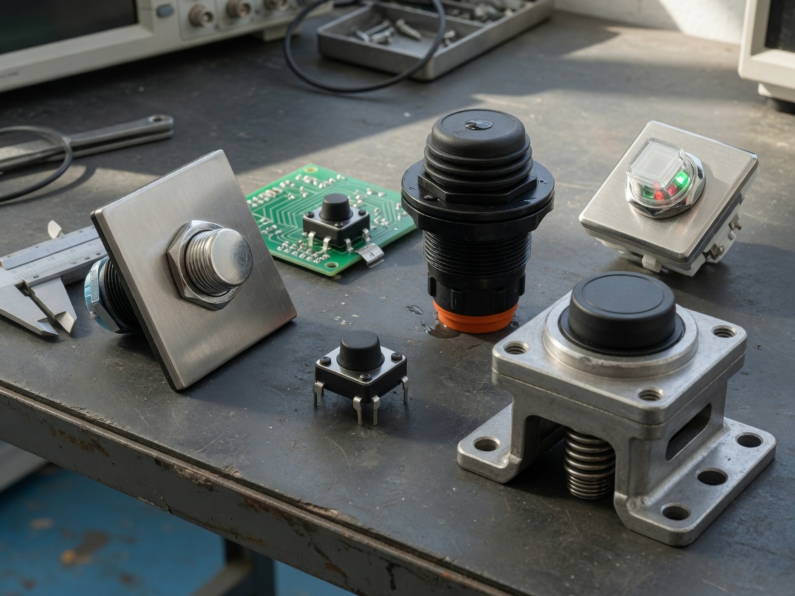
| Type | Typical size | Mounting | Current rating | Common application | IP rating |
|---|---|---|---|---|---|
| Standard panel mount | 12–22 mm | Panel hole | 1–10 A | Control panels, machinery | IP40–IP65 |
| Tactile / PCB mount switch | 3–12 mm | PCB through-hole / SMD | 50 mA–500 mA | Consumer electronics, Arduino | IP40 |
| IP67 waterproof | 16–22 mm | Panel hole + seal | 1–5 A | Garden, garage, marine | IP67 |
| LED illuminated | 16–22 mm | Panel hole | 1–5 A | Status indication, power illuminated push button on equipment panels | IP40–IP65 |
| Heavy-duty industrial | 22–40 mm | Panel hole / surface | 10–25 A | Motor starters, high-current non-illuminated push button on heavy plant | IP65–IP67 |
Choosing between standard and tactile variants
For PCB-based projects — Raspberry Pi enclosures, custom Arduino shields, home automation modules — a PCB mount switch (tactile switch) is the default choice. These components sit directly on the board, keep the assembly compact, and require no separate wiring. The trade-off is low current capacity; they are signal-level devices, not power switches. Attempting to switch a 12V relay coil directly through a standard tactile switch is borderline acceptable; switching a motor directly is not.
Ball-head and ergonomic actuator variants
A ball-head non-illuminated push button represents a pure mechanical, ergonomic control switch. Its simplified structure and extended actuator geometry reduce operator fatigue in repetitive-use environments such as production lines. The rounded actuator also reduces the risk of accidental actuation when an operator's gloved hand grazes the panel — a consideration that matters in UK manufacturing environments where PPE is mandatory.
Wiring a push to make switch: 12V DC vs 230V AC
Correct wiring is where theory becomes practice — and where errors become hazards. The mechanical action of a push to make switch is identical regardless of voltage, but the wiring approach, wire gauge, and safety precautions differ substantially between a 12V DC doorbell or car circuit and a 230V AC UK mains installation.
Wiring for 12V DC (vehicle, doorbell, low-voltage circuits)
In a basic 12V DC circuit — the most common scenario for DIY builders — the push to make switch is wired in series with the load. Follow this procedure:
- Disconnect the power source entirely before touching any wiring.
- Identify the two terminals on the push to make switch (most standard variants have two terminals; NO contact is confirmed by continuity test — zero resistance when pressed, open circuit at rest).
- Connect the positive supply wire to one terminal of the switch.
- Connect the other terminal to the positive input of your load (lamp, buzzer, relay coil, etc.).
- Connect the negative (ground) wire directly from the load to the battery or supply negative — the switch is only in the positive line.
- Use wire rated for at least 125% of the expected load current; for a 2 A load, use minimum 2.5 A rated cable.
- Reconnect power and verify operation: the load should activate only while the button is held.
In vehicle installations (12V or 24V DC), additional considerations apply: use automotive-grade tinned copper cable to resist vibration fatigue, secure the switch body with a locking nut rated for vibration environments, and consider a blade fuse inline to protect the circuit.
Wiring for 230V AC (UK mains)
Wiring a momentary contact switch into a 230V AC UK mains circuit — for example, a hard-wired doorbell transformer or a momentary action switch in a light circuit — requires strict adherence to BS 7671. This is not a task to approach casually. The switch must be rated for mains voltage (minimum 250V AC rating marked on the body) and must comply with applicable British Standards. Always isolate the circuit at the consumer unit, verify isolation with a calibrated test instrument, and work in accordance with Part P of the Building Regulations if the installation is in a dwelling.
The wiring sequence for a simple 230V momentary switch: the line (brown) conductor passes through the switch; the neutral (blue) connects directly to the load; the earth (green/yellow) connects to any metallic switch body or enclosure. Never interrupt the neutral conductor with a switch — this is a BS 7671 violation and creates a shock risk even when the load appears off.
Of course, there are situations where a competent DIY installer can legally carry out minor works under the Part P notification exemption — but for any new circuit or consumer unit work, a registered electrician is required in England and Wales.
UK compliance: BS 7671 and safety requirements
UK compliance requirements are a gap that most generic product guides simply ignore. For anyone specifying or installing a push to make switch in a UK electrical installation, BS 7671 (the 18th Edition IET Wiring Regulations, incorporating Amendment 2) is the authoritative standard. Several of its provisions directly affect switch selection and installation.
Key BS 7671 requirements for switch installations
Regulation 132.15 requires that every switch be suitable for its intended duty — meaning the voltage, current, and fault-level ratings of the selected switch must match or exceed the circuit parameters. An electronic push switch rated at 125V AC must never be installed in a 230V circuit, even temporarily. Additionally, Regulation 537.5 covers the specific requirements for control switches: they must interrupt the line conductor, be clearly identifiable, and be accessible for operation and maintenance.
For installations in zones with increased shock risk (bathrooms, swimming pools, outdoor locations), additional restrictions apply under BS 7671 Part 7. Switch IP ratings become mandatory requirements rather than optional enhancements — more on this in the next section.
CE and UKCA marking in 2026
Post-Brexit, the UKCA mark has fully replaced CE marking for products placed on the UK market. As of 2026, any push to make switch sold in Great Britain for use in a regulated electrical installation should carry UKCA marking and be accompanied by a Declaration of Conformity to the relevant electromagnetic compatibility and low-voltage directives as transposed into UK law. Procurement engineers should verify this documentation before approving a new component supplier — the absence of UKCA marking on a mains-rated switch is a direct compliance failure.
IP ratings and outdoor use in the UK
Britain's climate makes IP protection ratings a practical necessity, not a marketing embellishment. A standard indoor momentary push button switch will fail within months if installed in a garden gate intercom, a garage door control panel, or a shed light circuit exposed to rain and condensation.
Understanding IP65, IP67, and IP68
The IP (Ingress Protection) code defined by IEC 60529 uses two digits: the first for solid particle protection, the second for liquid ingress. For UK outdoor installations:
- IP65: Dust-tight; protected against water jets from any direction. Suitable for covered outdoor locations — a porch doorbell switch, for example — where direct rain contact is possible but submersion is not.
- IP67: Dust-tight; protected against temporary immersion up to 1 metre for 30 minutes. The minimum specification for garden installations subject to hosing down or surface flooding.
- IP68: Dust-tight; protected against continuous immersion beyond 1 metre. Specified for permanently submerged or marine applications.
Real-world testing in UK garden environments suggests IP65 is borderline adequate for sheltered positions and IP67 is the sensible minimum for any exposed installation. Why do buyers underspecify? Usually because IP67 components carry a price premium of roughly 30–60% over equivalent IP40 switches. In the long run, a single field replacement — including labour costs — almost always exceeds that price difference.
Gasket condition and long-term weatherproofing
Just as a waterproof watch loses its rating once the gasket degrades, an IP67 push to make switch can lose its ingress protection if the panel-mount seal is compressed incorrectly during installation or ages without replacement. The sealing gasket must sit flat against a smooth panel surface. Panel cutout burrs, paint overspray, or overtightening the locking ring all compromise the seal. In critical installations — a coastal property or an unheated outbuilding in Scotland — inspect and replace sealing gaskets every three to five years as part of routine maintenance.
Fault diagnosis: troubleshooting common problems
Even correctly specified and installed switches develop faults. The following systematic approach covers the most common failure modes observed in both consumer and light-industrial settings.
Step-by-step fault diagnosis procedure
- Isolate the circuit before any physical inspection. Verify isolation with a multimeter or voltage tester.
- Visual inspection: Look for discolouration, corrosion on terminals, cracked actuator body, or a damaged spring return mechanism.
- Continuity test: With the circuit de-energised, use a multimeter in continuity/resistance mode. At rest, the push to make switch should show open circuit (OL). When pressed, it should show near-zero resistance (typically under 0.5 Ω for a good contact). Higher resistance indicates contact oxidation or wear.
- Switch bounce check: If the connected load (relay, microcontroller input) appears to trigger multiple times per press, contact bounce is the likely cause. Verify with an oscilloscope or logic analyser.
- Overcurrent inspection: Blackening or pitting of the contacts — visible only if the switch body can be opened — indicates the switch has been operating at or above rated current. Check the load current against the switch specification.
- Wiring integrity: Tug-test each terminal connection. A surprisingly common fault in DIY installations is a conductor that appears secure but is only lightly gripping the terminal.
- Replacement decision: If continuity is intermittent, contact resistance exceeds 1 Ω, or the actuator travel feels spongy rather than crisp, replace the switch. Momentary contact switch components are low-cost enough that repair is rarely economical.
Common fault patterns and their causes
Switch chatter or intermittent contact in a micro switch application is almost always a sign of mechanical wear or contamination — not an electrical fault further down the circuit. Conversely, a switch that stays permanently open (never conducts even when pressed) has usually suffered a broken spring or a seized actuator, often from ingress of moisture or a corrosive atmosphere. A permanently closed fault — where the switch conducts even without being pressed — is far less common in NO-type switches but can occur if the actuator has jammed in the depressed position or if the contacts have welded together due to an overcurrent event.
It is worth acknowledging a limitation here: field diagnosis without test equipment is inherently uncertain. A simple digital multimeter resolves the majority of push to make switch faults in under five minutes. If your toolkit does not include one, that is the single most impactful upgrade you can make before tackling any electrical fault-finding task.
Choosing the right push to make switch: a practical summary
The right push to make switch is the one that matches your voltage, current, environment, and form factor — in that order of priority. Voltage and current ratings are non-negotiable safety parameters. Environment dictates the required IP rating. Form factor (panel mount, PCB mount switch, surface mount) is determined by your mechanical design. LED illumination and actuator style are the last considerations, not the first.
Just like choosing the right tyre for a car — performance on dry roads counts for nothing if the compound fails in wet conditions — selecting a switch purely on panel aesthetics while ignoring IP rating or current rating is a recipe for premature failure. In 2026, with UK supply chains offering UKCA-compliant, RoHS-conforming components at competitive prices, there is no engineering justification for accepting a mismatched specification.
The push to make switch remains one of the most fundamental components in electrical switch types — present in everything from a child's toy to a North Sea platform control panel. Getting the selection right the first time saves cost, reduces downtime, and, in mains voltage applications, protects lives.
Frequently asked questions
Q: What is the difference between a push to make switch and a push to break switch?
A: A push to make switch has normally open contacts — the circuit is open at rest and closes when pressed. A push to break switch has normally closed contacts — the circuit is closed at rest and opens when pressed. Confusing the two inverts your circuit logic, which is the most common switch selection error in the industry.
Q: Can I use a push to make switch on UK 230V mains?
A: Yes, provided the switch carries a minimum 250V AC voltage rating, is UKCA-marked, and the installation complies with BS 7671 — specifically, only the line conductor should be switched, never the neutral. For mains work in a dwelling, Part P of the Building Regulations also applies.
Q: What IP rating do I need for an outdoor push to make switch in the UK?
A: IP67 is the recommended minimum for any exposed outdoor location — gardens, garages, gate entry systems. IP65 is acceptable for sheltered positions where water jets are unlikely. Standard indoor switches (IP40) will corrode and fail rapidly in damp UK outdoor conditions.
Q: Why does my push to make switch seem to register multiple presses in a microcontroller project?
A: This is contact bounce — the contacts physically rebound multiple times within milliseconds of touching. Solve it in software with a 10–50 ms debounce delay, or in hardware with a simple RC filter (10 kΩ resistor and 100 nF capacitor). Both methods are standard practice in Arduino and Raspberry Pi projects.
Q: Is a tactile switch the same as a push to make switch?
A: Yes, functionally. A tactile switch is a compact PCB mount variant of the momentary push button switch family — it uses the same normally open, spring return mechanism. The term "tactile" refers to the audible and physical click feedback on actuation, and is most commonly used in consumer electronics and PCB design contexts rather than industrial panel wiring.
Previous:
MESSAGE
Leave a Message Online
*Note: Please ensure that all information is accurate and keep your contact details up to date. We will get in touch with you as soon as possible.
Contact Information
Contact: Manager Zhang (Business Department)
Phone:+86 0769-86302535-8808
Mobile phone:+86 18025227237
E-mail:hosong@hosong.cn
Address: No. 2, Industrial Road No. 1, Xiajiangcheng, Gaobu Town, Dongguan City, Guangdong Province, China

Scan to add the official account
Learn more about WeCom...
Want to learn more about the company’s products and information?
Guangdong HOSONG Button Manufacturing Co., Ltd.
Phone:+86 18025227237 / +86 0769-86302535
WhatsAPP:+86 18025227237
Email:hosong@hosong.cn
Address: No. 2, Industrial Road No. 1, Xiajiangcheng, Gaobu Town, Dongguan City, Guangdong Province, China
HOSONG International (Hong Kong) Limited
Address: Room 15, 11th Floor, Wah Wai Plaza, No. 1008 Tai Nam Sai Street, Lai Chi Kok, Kowloon, Hong Kong
Phone:0852-30780831
Fax:0852-30775900