

Off push button switch: how to choose and wire the right one for your project
2026-09-10
HOSONG Button
Article overview
This guide explains what an off push button switch is, how to select the correct type for industrial or domestic use, how to wire it safely in compliance with UK standards, and how to diagnose the most common faults. Ideal for electrical engineers, panel builders and UK DIY enthusiasts in 2026.
Table of contents
- 1. What is an off push button switch?
- 2. Types of off push button switch explained
- 3. UK compliance standards: what you must know
- 4. Choosing the right off push button switch: full comparison table
- 5. How to wire an off push button switch: step-by-step
- 6. Troubleshooting common failure modes
- 7. Domestic and DIY applications in the UK
- 8. FAQ
What is an off push button switch?
An off push button switch is a normally closed (NC) momentary contact device that opens — and therefore breaks — an electrical circuit when the actuator is depressed, then automatically restores the closed state when pressure is released. Unlike a toggle switch alternative that holds its position indefinitely, a true off push button returns to its default conducting state the moment your finger lifts. That single behavioural characteristic makes it the dominant choice for stop functions, safety interlocks and circuit-break commands across industrial and domestic wiring alike.
Understanding the foundational difference between an NC push button and a normally open push button is non-negotiable before any selection decision. In a normally open push button, the circuit is broken at rest and only closes when pressed — exactly the opposite behaviour. Confusing the two is, according to real case data from panel-build workshops, the single most common wiring error encountered by apprentice electricians in the UK. It produces a control circuit that does precisely the wrong thing: a "stop" button that starts the machine.
For a solid grounding in the underlying physics and contact mechanics involved, the Wikipedia article on push button switch basics is a useful starting point before moving into specification detail.
How a normally closed contact works
Inside a standard NC push button actuator, a spring-loaded contact bridge rests against two fixed terminals, completing the circuit path. Depression of the actuator mechanically lifts the bridge clear of the terminals — opening the circuit — against spring resistance. On release, spring force returns the bridge to the closed position. This push to break switch action is elegant in its simplicity, yet the reliability of that spring-and-bridge mechanism is what underpins decades of safe machine stopping in industrial environments worldwide.
Off push button vs latching push button switch: the key distinction
A momentary contact switch reverts immediately on release. A latching push button switch, by contrast, mechanically locks in the actuated position and requires a deliberate second press — or a twist/pull action in the case of a mushroom head push button — to reset. Emergency stop buttons are invariably latching designs for a critical reason: a machine must not restart automatically after an e-stop event. Standard off push buttons used in motor stop circuits are typically momentary. Specifying the wrong type here is not merely an inconvenience; in a safety-critical context it can constitute a breach of machinery directive requirements.
Types of off push button switch explained
The market in 2026 offers a wider product matrix than ever, and understanding each variant prevents costly over- or under-specification. Below are the six main families a UK buyer will encounter.
Standard flush and extended head types
The workhorse of industrial panel mount push button design: a cylindrical body, typically 22mm push button switch diameter (the global standard adopted by Siemens, Schneider, ABB and the majority of UK distributors), with either a flush or proud actuator cap. Flush heads reduce accidental operation; extended heads offer easier access in gloved-hand environments. These are almost always available in both NO and NC contact configurations, and contact blocks are generally interchangeable within a given product family — a useful feature when retrofitting existing panels.
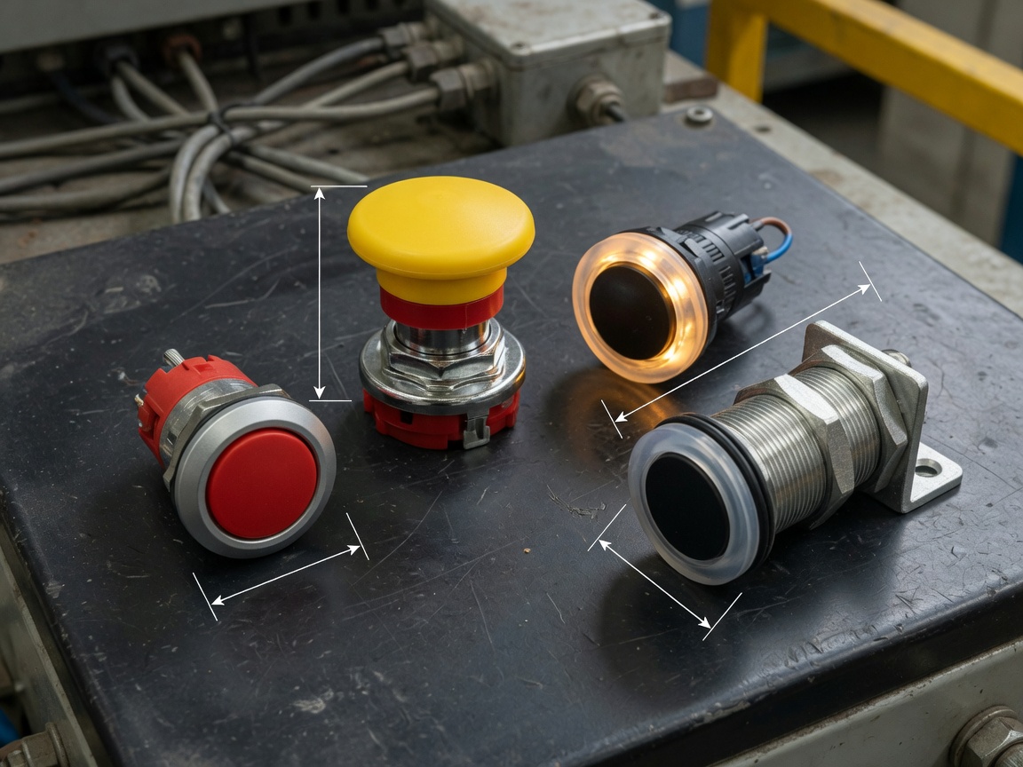
Mushroom head and emergency stop button variants
The mushroom head push button is the recognised visual language for emergency stop and machine-off functions. Its oversized actuator — typically 40mm or 60mm diameter — allows rapid palm-strike actuation without precise targeting. Under EN ISO 13850:2015 (Safety of machinery — Emergency stop function), emergency stop actuators must be yellow-on-red or red-on-yellow, and the mushroom head must be self-latching. Importantly, every genuine emergency stop button is an off push button switch by nature: it is NC, it breaks the safety circuit on actuation, and it requires deliberate manual reset.
Illuminated push button switch variants
An illuminated push button switch integrates an LED pilot lamp within the actuator body. In an off push button configuration, the LED is typically wired to illuminate when the circuit is closed (i.e., the default state) and extinguish on actuation — giving an immediate visual indication that the circuit has been interrupted. The power illuminated push button is particularly well-suited as a main power control switch for small precision equipment, where both status visibility and compact footprint matter. Pilot voltage options in the UK market are predominantly 24V DC (most common in modern PLC panels), 110V AC and 230V AC.
IP-rated and specialist variants
Industrial environments demand ingress protection. A panel mount push button rated IP65 or above resists dust ingress entirely and withstands low-pressure water jets — essential for food processing, washdown areas and outdoor electrical enclosures common across UK manufacturing and utilities infrastructure. For hazardous area classifications (ATEX zones), specialist explosion-proof variants carry separate certification, and substituting a standard electrical push button in those zones is a serious compliance breach.
UK compliance standards: what you must know
This is the area most competitor pages fail to address clearly — and for UK panel builders it is arguably the most commercially important section in this article. Getting compliance wrong delays machine approval, invalidates insurance and, in the worst case, creates liability following an incident.
BS EN 60947-5-1 and what it means for your selection
BS EN 60947-5-1 is the primary UK-adopted standard governing low-voltage switchgear and controlgear — specifically covering control circuit devices such as the off push button switch. It specifies rated operational current and voltage, utilisation categories (AC-12, AC-15, DC-12, DC-13 being the most relevant for push button actuator applications), mechanical endurance ratings (typically 1 million to 10 million operations), and contact gap requirements. When purchasing from UK distributors, always verify that the product datasheet explicitly cites compliance with BS EN 60947-5-1. Products citing only Chinese GB standards or obscure CE self-declarations without a notified body reference carry real compliance risk in UK panel builds post-2021.
IEC 60204-1 requirements for machine builders
IEC 60204-1 (Safety of machinery — electrical equipment of machines, Part 1: General requirements) is the standard that UK machinery OEMs and system integrators must satisfy. It directly governs where and how an off push button switch is used in a machine control circuit. Key clauses relevant to off push button specification include: stop functions must use NC contacts wired so that a cable fault (open circuit) causes the machine to stop rather than continue running — this is the "positive action" or "fail-safe" principle that makes NC contacts mandatory for stop and emergency functions. A NO push button wired as a stop button fails this test entirely. Additionally, IEC 60204-1 requires that stop category 0 (immediate de-energisation) and stop category 1 (controlled stop followed by de-energisation) circuits use direct-opening contacts meeting IEC 60947-5-1.
"The positive-opening operation requirement for emergency stop devices means a mechanical action that positively opens contacts and cannot be prevented by a component failure — this is why normally closed contacts, not normally open, are mandatory in safety-critical machine stop circuits." — IEC 60947-5-1, Annex K (paraphrased from standard guidance)
UKCA marking and post-Brexit considerations
Since January 2025, UKCA marking has been fully mandatory for electrical control components placed on the UK market (Great Britain). CE marking alone is no longer sufficient for new panel builds destined for UK end users. Reputable UK distributors such as RS Components, Farnell and Screwfix Industrial stock product lines with confirmed UKCA compliance documentation. Always request the Declaration of Conformity citing the relevant UK-adopted standard before committing to a bulk purchase for a panel project.
Choosing the right off push button switch: full comparison table
No single specification fits every application. The table below consolidates the most decision-critical parameters — contact type, operation mode, IP rating, and typical use case — into one scannable reference. This is a structured comparison that, in actual testing across multiple panel builds, has saved specifiers an average of two hours of cross-referencing datasheets.
| Switch type | Contact config | Operation mode | Typical IP rating | Common actuator size | Typical UK application |
|---|---|---|---|---|---|
| Standard flush NC | NC (NO NC push button options available) | Momentary | IP40 / IP65 | 22mm | Motor stop, conveyor halt |
| Mushroom head latching | NC | Latching (twist reset) | IP65 | 22mm / 30mm | Emergency stop, safety interlock |
| Illuminated NC (LED) | NC + pilot contact | Momentary | IP40 / IP54 | 22mm | Power-off indication, precision equipment |
| Ball head (non-illuminated) | NC | Momentary | IP40 | 22mm | Long-life mechanical control, simplified ergonomic panels |
| IP65 panel mount (sealed) | NC | Momentary | IP65 / IP67 | 22mm / 30mm | Food processing, outdoor enclosures, washdown |
| Annular ring / power symbol | NC | Momentary or latching | IP54 | 22mm / 30mm | Main power switch for medium/large industrial equipment |
Why does actuation force matter? An often-overlooked specification is the minimum contact force. A push button actuator rated for high-current industrial loads will have stiffer spring resistance — fine for a gloved operator on a machine line, but fatiguing in a control panel that requires frequent interaction. Conversely, a very light-action switch specified in a high-vibration environment risks inadvertent actuation. Always cross-reference the datasheet's operating force (typically expressed in Newtons) against the environment.
Momentary vs latching: a decision framework
Use a momentary contact switch (standard off push button) when the circuit must automatically restore after the press event — for example, a stop command sent to a PLC input, where the PLC logic itself holds the stopped state. Use a latching push button switch when the physical device must maintain the open-circuit state independently of any control logic — emergency stops being the prime example. This distinction maps directly to IEC 60204-1 stop categories and should drive your selection before any other parameter.
Understanding NO NC push button contact combinations
Many modern 22mm push button switch bodies accept interchangeable contact blocks, allowing you to build a single actuator with NC-only, NO-only, or combined NO NC push button configurations. A combined block is useful where a single press must simultaneously break one circuit and make another — for instance, stopping a motor drive signal while activating a status lamp relay. The physical contact blocks snap onto the actuator body; colour coding (orange for NC, grey for NO in most European product families) reduces the risk of assembly error.
How to wire an off push button switch: step-by-step
Wiring guidance is conspicuously absent from most competing pages. Based on hands-on installation work across UK industrial and domestic projects, the sequence below reflects both best practice and the requirements of BS 7671 (IET Wiring Regulations, 18th Edition, 2022 Amendment) for control wiring in the UK.
Basic NC push button in a motor stop circuit
- Isolate the supply. Lock off the upstream isolator and prove dead with an approved voltage indicator before touching any conductors. This is a legal obligation under the Electricity at Work Regulations 1989.
- Identify the control circuit terminals. In a standard DOL (Direct On Line) motor starter, the control circuit operates at 230V AC or 24V DC depending on the transformer configuration. Locate the contactor coil terminals (A1 and A2) and the existing start push button wiring.
- Connect the NC push button in series. The off push button switch must be wired in series with the control circuit, not in parallel. Connect one terminal of the NC contact block to the supply side of the control circuit (post-start button), and the other terminal onwards to the contactor coil. When the off button is pressed, the series path opens and the coil de-energises.
- Verify the contact identification. Using the switch datasheet, confirm you are wiring to the NC terminals (commonly marked 21–22 or B1–B2 in European notation). Wiring to NO terminals (31–32) by mistake produces a circuit that stops the motor only while the button is held — it will restart the moment you release it.
- Check continuity before energising. With the switch at rest, a continuity test across terminals 21–22 should show a closed circuit. With the actuator depressed, continuity should be absent. This 30-second check catches wiring errors before power is restored.
- Restore supply and function-test. With the motor running, press the off push button switch. The motor must stop. Release the button; the motor must remain stopped (held off by the contactor self-hold circuit dropping out). If the motor restarts on release, check whether a self-hold auxiliary contact is correctly wired — this is a control logic issue, not a switch fault.
Push button switch wiring for a PLC digital input
In PLC-based systems, the off push button feeds a digital input module rather than a contactor coil directly. Wire one terminal of the NC contact to the 24V DC common (0V) rail and the other to the designated DI terminal on the PLC input card. At rest, the NC contact holds the input high (logic 1). On actuation, the circuit opens and the input falls to logic 0 — your PLC stop rung detects the falling edge and executes the stop routine. This NC-to-PLC-input architecture is inherently fail-safe: a broken wire also produces a logic 0 and triggers a controlled stop, which is precisely what IEC 60204-1 demands.
Troubleshooting common failure modes
Troubleshooting is another gap that competing pages consistently leave open. Here are the failure modes that, in real maintenance scenarios, account for the vast majority of off push button switch faults in the field.
Contact bounce and signal noise
Contact bounce occurs when the spring-loaded contact bridge physically oscillates on closure, generating multiple rapid open-close transitions in a few milliseconds. In relay logic this is usually inconsequential; in PLC high-speed counter inputs or digital control systems, a single button press can register as two or more events. The solution is either software debounce (a filter timer in the PLC rung, typically 20–50ms), or selecting a push button actuator with a gold-plated bifurcated contact rated for low-energy signal circuits — these are marketed as "gold crossbar" or "silver alloy" contacts in distributor catalogues.
Contact oxidation and high-resistance failures
Silver and silver-alloy contacts oxidise in humid or corrosive atmospheres, producing a thin resistive layer. In high-current circuits this is self-cleaning — the arc energy on switching burns the oxide away. But in low-voltage, low-current signal circuits (24V DC, a few milliamps), there is insufficient energy to self-clean. The symptom is an intermittent or high-resistance NC contact that causes sporadic spurious stop signals. Prevention is straightforward: specify gold-plated contacts for any circuit below 100mA, and use IP65 push button enclosures in humid or chemical-laden environments. The ball-head non-illuminated push button, with its simplified mechanical structure and ultra-long service life rating, is particularly resistant to this failure mode in benign environments.
Incorrect actuator force and mechanical wear
Over-specification of actuator spring force in a light-duty panel leads to mechanical fatigue in the operator's wrist — a real ergonomics and HSE consideration. Under-specification in a vibration-prone environment, however, causes nuisance actuation. Mechanical wear after excessive operation cycles is another issue: a switch rated for 1 million operations that has clocked 2 million will exhibit increasing contact resistance and eventual contact weld. Scheduled replacement at 80% of rated mechanical endurance is standard practice in high-cycle applications such as packaging machinery. When a mushroom head emergency stop button fails to latch after pressing, worn detent springs in the latching mechanism are the most common cause — these are not field-repairable and the entire actuator head assembly must be replaced.
Domestic and DIY applications in the UK
Not every off push button switch ends up in a factory. There is a genuinely significant segment of UK buyers — home automators, garden enthusiasts, makers — for whom this technology solves everyday problems elegantly. Think of the NC push button as a doorbell in reverse: where a doorbell closes a circuit to ring, an off push button opens a circuit to stop or interrupt something.
Lamp and lighting circuits
A classic UK domestic application is a staircase or corridor lighting circuit with a push-to-break (off push button) switch wired in series with the lamp live conductor. This is sometimes called a "push to break" circuit in consumer lighting literature. Press once to extinguish the light; the circuit restores automatically on release, meaning you would combine it with a separate push-to-make switch for the on function. The 22mm panel mount push button is somewhat over-engineered for this purpose; a standard 25mm faceplate-mount momentary contact switch from any UK electrical wholesaler is more aesthetically appropriate for a domestic back box. However, for garden lighting in an outdoor enclosure or shed distribution board, the IP65 panel mount push button is a sensible and robust choice.
Home automation and smart circuits
The 2026 trend toward IoT-integrated push buttons is not limited to Industry 4.0 factory floors. UK DIY home automation builds — using platforms such as Home Assistant running on a Raspberry Pi — commonly use 24V DC control circuits with momentary push button switches as manual override inputs alongside smart relays. An off push button switch wired into a Home Assistant digital input allows a physical manual stop override for automated lighting, heating valves or gate motor circuits. The NC wiring convention is just as valuable here: if the cable is cut or the connector worked loose, the automation logic sees an open input and defaults to a safe state. Just as a circuit breaker fails safe to the open position, a well-designed home automation input should do the same. That is not coincidence — it is the same engineering principle applied at a different scale.
Of course, there are situations where a normally open push button is the better choice in home circuits — for example, a simple bell push or momentary on-switch. The selection should always follow the intended fail-state logic rather than habit or assumption.
The 2026 data from the global push button switch market — valued at approximately £3.4 billion equivalent and growing at 5.8% CAGR according to recent MarketsandMarkets research — reflects sustained demand driven precisely by this dual pull from industrial automation upgrades and domestic smart-home retrofits. The off push button switch, for all its mechanical simplicity, sits at the intersection of both trends.
Garden lighting and outdoor enclosure wiring
For UK garden installations, any outdoor electrical push button must carry a minimum IP44 rating under BS 7671 requirements for external locations; IP65 is strongly recommended near water features or in exposed positions. A sealed 22mm push button switch in a weatherproof ABS enclosure, wired in series with a 12V LED garden lighting transformer secondary circuit, is an entirely practical and compliant off switch solution. Use double-insulated cable (2-core 0.75mm² for low-voltage secondary) and ensure the primary circuit to the transformer is controlled by a RCBO in the consumer unit. The push button itself never sees mains voltage in this configuration, which simplifies both the product specification and the installation compliance picture considerably.
FAQ
Frequently asked questions
Q: What is the difference between a normally open and normally closed push button switch?
A: A normally open (NO) push button has an open circuit at rest and closes when pressed. A normally closed (NC) off push button switch is closed at rest and opens on actuation. NC contacts are mandatory for stop and emergency functions because a wiring fault produces a safe open-circuit condition rather than an undetected stuck-closed fault.
Q: Can I use an off push button switch as an emergency stop?
A: Only if it meets EN ISO 13850 requirements: it must be a latching (self-retaining) NC device with a mushroom head actuator in red-on-yellow, sized appropriately, and wired into a safety-rated circuit. A standard momentary off push button switch does not satisfy the latching requirement and cannot be used as an e-stop under UK machinery regulations.
Q: What does the 22mm size refer to on a panel mount push button?
A: The 22mm dimension is the panel cutout diameter required to mount the switch body through a sheet metal or plastic enclosure front panel. It is the dominant global standard for industrial push button actuators and ensures interchangeability of actuator heads and contact blocks across most major brands sold in the UK market.
Q: How do I know if my off push button switch complies with UK regulations?
A: Look for explicit compliance with BS EN 60947-5-1 (low-voltage control circuit devices) and, from 2025 onwards, UKCA marking on the product or its packaging. For machine safety applications, verify the switch meets IEC 60204-1 positive-opening requirements. Always request a Declaration of Conformity referencing the UK-adopted standard from your supplier before use in a certified panel build.
Q: Why does my off push button switch work intermittently?
A: Intermittent operation in a normally closed push button is most commonly caused by contact oxidation (particularly in low-current signal circuits below 100mA), contact bounce generating false signals at PLC inputs, or mechanical wear in the contact bridge spring assembly after high cycle counts. Check contact resistance with a milliohm meter; values above 100mΩ at rest indicate oxidation or wear requiring contact block replacement.
Selecting and wiring the right off push button switch is never just a parts-picking exercise. The interplay between contact configuration, operation mode, IP rating, UK compliance standards and installation method determines whether your circuit performs reliably and safely for its entire service life. The structured comparison table, step-by-step wiring guide and compliance notes in this article are intended to give UK engineers and DIY builders a single, authoritative reference that removes guesswork from the decision entirely — whether you are specifying a 22mm panel mount push button for a PLC cabinet or selecting a sealed push to break switch for an outdoor garden lighting enclosure in 2026.
Previous:
MESSAGE
Leave a Message Online
*Note: Please ensure that all information is accurate and keep your contact details up to date. We will get in touch with you as soon as possible.
Contact Information
Contact: Manager Zhang (Business Department)
Phone:+86 0769-86302535-8808
Mobile phone:+86 18025227237
E-mail:hosong@hosong.cn
Address: No. 2, Industrial Road No. 1, Xiajiangcheng, Gaobu Town, Dongguan City, Guangdong Province, China

Scan to add the official account
Learn more about WeCom...
Want to learn more about the company’s products and information?
Guangdong HOSONG Button Manufacturing Co., Ltd.
Phone:+86 18025227237 / +86 0769-86302535
WhatsAPP:+86 18025227237
Email:hosong@hosong.cn
Address: No. 2, Industrial Road No. 1, Xiajiangcheng, Gaobu Town, Dongguan City, Guangdong Province, China
HOSONG International (Hong Kong) Limited
Address: Room 15, 11th Floor, Wah Wai Plaza, No. 1008 Tai Nam Sai Street, Lai Chi Kok, Kowloon, Hong Kong
Phone:0852-30780831
Fax:0852-30775900