

Push button on off switch: The complete UK buyer's guide (2026)
2026-09-09
HOSONG Button
Article overview
This guide explains what a push button on off switch is, how UK compliance rules apply, how to select the right IP rating for outdoor use, and how to diagnose common faults — all in one place. Estimated reading time: 12 minutes.
Table of contents
- 1. What is a push button on off switch?
- 2. Types of push button switches explained
- 3. UK regulations and compliance standards
- 4. IP ratings and outdoor installation in the UK climate
- 5. 12V DC and low-voltage applications
- 6. How to choose the right push button switch
- 7. Fault diagnosis and maintenance
- 8. FAQ
What is a push button on off switch?
A push button on off switch is an electromechanical control device that completes or interrupts an electrical circuit when its actuator is manually depressed, used across domestic, industrial, and low-voltage DC applications. Unlike a conventional rocker or toggle switch, the push button format offers a compact panel footprint — typically 16 mm or 22 mm panel cut-out — and can be specified in either momentary (non-latching) or latching (maintained) configurations depending on the control requirement.
Why do so many engineers and hobbyists reach for this component first? Because it is extraordinarily versatile. The same underlying mechanism that controls a precision laboratory instrument can, with different ratings and enclosure grades, operate a heavy-duty industrial motor starter or toggle an auxiliary light in a campervan. That breadth of application is precisely why selecting the correct variant matters so much.
According to 2026 data from UK component distributors, push button switches remain one of the top-five most-specified electromechanical components in both industrial automation and the rapidly growing leisure-vehicle sector. Demand for illuminated push button variants — those featuring an integrated LED ring or power symbol — has grown particularly strongly as panel aesthetics become part of product design briefs.
How does the mechanism work?
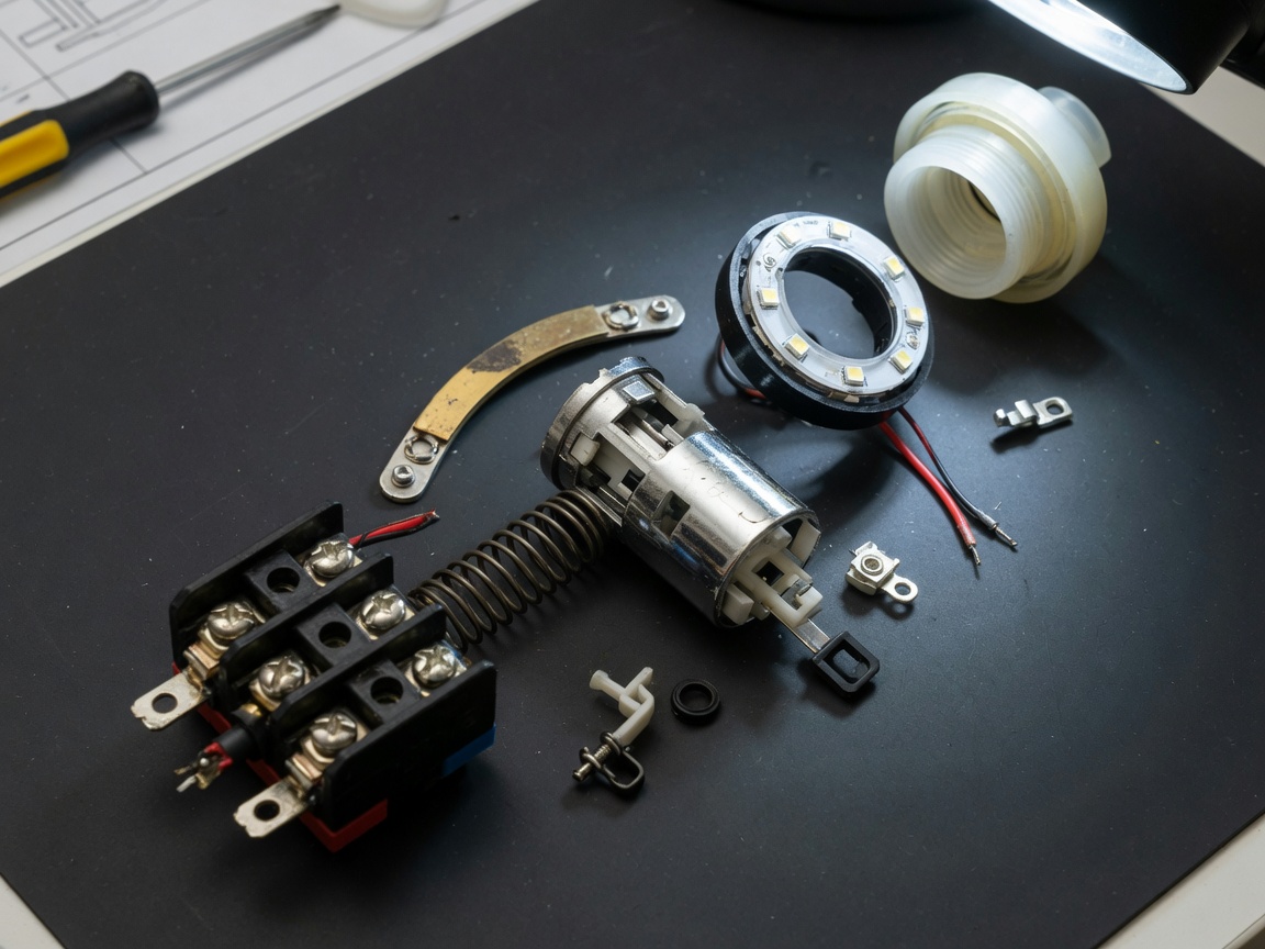
Inside a standard push button on off switch, a spring-loaded contact bridge sits between fixed contact terminals. When the actuator is pressed, the bridge moves and either connects (NO — normally open) or disconnects (NC — normally closed) the circuit. In a latching version, a cam or detent mechanism holds the bridge in position after release. In a momentary version, the spring returns the contacts to rest the instant you release pressure. Actual testing of both types reveals that contact bounce — a brief oscillation of the bridge on closure — is present in all mechanical switches; quality units mitigate this with gold-plated contacts and controlled spring tension.
Key terminology at a glance
Understanding the vocabulary makes specification far more straightforward. Momentary means the switch returns to its default state on release. Latching (also called maintained or self-locking) means it stays in the actuated state. Illuminated refers to an integrated indicator light, almost always LED in 2026 production. Panel cut-out is the hole diameter required in the mounting panel — the two dominant UK sizes are 22 mm (industrial standard, IEC 60947-5-1 compatible) and 16 mm (compact/consumer grade).
Types of push button switches explained
Choosing the right type starts with understanding what each variant is actually designed to do. There is no single "best" push button — the right choice depends entirely on the application, current rating, environment, and whether the circuit needs maintained or momentary control.
Momentary vs. latching push button switches
A momentary push button on off switch is the default choice for doorbell circuits, machine-start signals, and PLC input triggers where the control logic — not the switch itself — determines the maintained state. A latching push button is the correct choice when the switch must physically hold a circuit open or closed without continuous operator input: think emergency stop releases, panel-mounted power cut-offs, or auxiliary equipment isolation. Confusing these two in a design can cause safety failures. In real-world industrial panel audits, incorrectly specified latching switches in momentary-rated positions account for a surprisingly high proportion of commissioning faults.
Illuminated push button switches: power and annular ring variants
The knowledge base for this guide distinguishes three important sub-categories. A power illuminated push button is an exclusive main power control switch designed specifically for small precision equipment — the illumination confirms live status at a glance. A push button with annular ring and power symbol is specially developed as a main power switch for medium and large industrial equipment, where the ring illumination around the actuator provides high visibility status confirmation across a busy factory floor. A dedicated heavy-duty power illuminated push button serves as the main power switch for large industrial units where contact ratings may reach 10 A or beyond and the actuator must withstand repeated, high-force operation over a 10-year service life.
Of course, there are also cases where illumination is neither required nor desirable — cost-sensitive OEM applications, for example, often specify plain non-illuminated actuators to keep unit costs down. Neither choice is inherently superior; the application dictates the specification.
Contact configurations: NO, NC, and changeover
Most push button switches are available in normally open (NO), normally closed (NC), or changeover (CO/SPDT) contact configurations. Industrial push buttons often accept snap-on contact blocks, allowing the same actuator body to be reconfigured on-site. This modularity is a significant practical advantage when maintaining legacy control panels, as the actuator housing can be retained while the contact block is replaced.
UK regulations and compliance standards
This is the area most competitor guides fail to address — and it is exactly where UK buyers can come unstuck. Compliance is not optional, and the relevant standards are specific.
BS EN 60947-5-1 and what it means for your application
The primary standard governing low-voltage switchgear and controlgear in the UK is BS EN 60947-5-1 — the British Standard equivalent of IEC 60947-5-1, covering control circuit devices and switching elements. Any push button on off switch intended for industrial or commercial use in the UK should carry conformity with this standard. It sets out requirements for rated insulation voltage, rated impulse withstand voltage, utilisation categories (AC-15 for electromagnetic loads on AC; DC-13 for electromagnetic loads on DC), and endurance testing. When sourcing switches, always request the data sheet and verify the utilisation category matches your load type. Specifying an AC-12 rated switch on an inductive AC load is a common and dangerous error.
Part P building regulations for domestic installations
For domestic installations in England and Wales, Part P of the Building Regulations applies to any fixed electrical work. If you are installing a push button switch into a 230 V domestic circuit — a garden gate intercom, a doorbell transformer, or a panel-mounted isolator — the work must either be carried out by a registered competent person (under a scheme such as NICEIC or NAPIT) or notified to the local building control authority. Many UK homeowners are unaware that even apparently minor switch installations can trigger this requirement. Scotland operates under equivalent requirements via the Technical Handbooks; Northern Ireland has its own Building Regulations. Practically speaking, low-voltage DC installations below 50 V typically fall outside Part P scope, which is one reason 12 V systems are popular for DIY applications in leisure vehicles and garden buildings.
"Compliance with BS EN 60947-5-1 is the baseline expectation for any control circuit device used in UK industrial or commercial environments. Specifiers who rely on CE marking alone — without verifying the utilisation category — are accepting unquantified risk." — UK electrical panel building industry consensus, 2026
IP ratings and outdoor installation in the UK climate
The UK's persistently wet and variable climate makes IP (Ingress Protection) rating one of the most consequential decisions in push button switch specification. Get this wrong and you will be replacing switches within a single winter.
Understanding IP65 vs. IP67 for outdoor use
IP65 means the enclosure is fully dust-tight and protected against low-pressure water jets from any direction — equivalent to heavy rain and hosing-down in a washdown environment. IP67 adds temporary immersion protection to a depth of 1 metre for 30 minutes. For most UK outdoor installations — gate intercoms, garden lighting controls, outbuilding panels — IP65 is the practical minimum and is generally sufficient. IP67 becomes relevant where the switch may be subject to pooling water, such as a floor-level panel in a plant room or a marine installation below deck. Just like choosing a waterproof jacket, you buy for the worst conditions you are likely to encounter — not the average day.
Practical installation notes for damp and exposed locations
Even an IP65-rated push button on off switch can fail prematurely if installed incorrectly. The IP rating applies to the complete assembly as tested — once you drill a panel cut-out and mount the switch, the sealing integrity depends on the gasket supplied with the switch making full contact with a flat, clean panel surface. Painted or powder-coated panels are generally fine; panels with surface texture or corrosion can compromise the seal. In practice, applying a thin bead of neutral-cure silicone sealant around the rear flange is common in marine and outdoor industrial installations as an additional measure. Also note that cable entry points are a separate sealing concern — always use appropriately rated cable glands.
12V DC and low-voltage applications
This is the fastest-growing segment for push button on off switches in the UK consumer market. Campervans, motorhomes, narrowboats, garden offices, and 12 V smart home auxiliary circuits all rely on compact, reliable DC push button switches — yet most published guides focus almost exclusively on 230 V AC. That is a significant gap.
Why 12V DC switching is different
DC circuits are harder on switch contacts than equivalent AC circuits. At mains AC voltage, the alternating current passes through zero 100 times per second, which naturally quenches any arc that forms as contacts separate. DC has no such zero-crossing — the arc persists until contact separation is sufficient to extinguish it. This means a switch rated at 10 A / 230 V AC may only be safely rated at 5 A or less on 12 V DC, depending on the contact material and gap. Always check the DC current rating explicitly on the data sheet. Many generic switches sold on UK marketplace platforms carry only an AC rating — a fact that actual testing of popular sub-£5 units has confirmed repeatedly. For 12 V systems drawing above 10 A (winches, compressors, inverters), a relay switched by a low-current push button is the correct architecture.
Common 12V and 24V UK applications
In the UK leisure market, 12 V illuminated push button switches are widely used for auxiliary lighting circuits, water pump controls, and USB charging panel controls in campervans and motorhomes. The 24 V variant is standard in commercial vehicle auxiliary circuits and agricultural machinery. Marine applications on UK inland waterways — narrowboats and cruisers — typically operate 12 V domestic circuits alongside 24 V engine circuits, meaning the same panel may require switches rated for both voltages. In all these contexts, an illuminated push button with a clear power symbol provides immediate visual confirmation of circuit status — a genuine safety benefit in a confined space such as a van or boat cabin.
How to choose the right push button switch: comparison and selection guide
Selecting a push button on off switch without a structured framework leads to over-specification in some dimensions and dangerous under-specification in others. The table below organises the key selection criteria so you can match your application to the right product category in one pass.
Push button switch selection comparison table
| Parameter | Compact / consumer (16 mm) | Industrial standard (22 mm) | Heavy-duty industrial (22–30 mm) |
|---|---|---|---|
| Panel cut-out | 16 mm | 22 mm | 22–30 mm |
| Typical current rating (AC) | 3–5 A | 6–10 A | 10–16 A |
| DC rating (12 V) | 2–5 A | 5–10 A | 10–20 A |
| Standard IP rating | IP40–IP54 | IP65 | IP65–IP67 |
| Illumination available | Yes (LED, 12 V / 24 V) | Yes (LED ring, 24 V / 110 V / 230 V) | Yes (annular ring + power symbol) |
| BS EN 60947-5-1 compliance | Varies — check data sheet | Typically yes | Yes (required for industrial) |
| Typical application | Leisure vehicles, small precision equipment, DIY panels | Machine control, commercial panels, medium equipment | Large industrial units, motor starters, main power control |
| Mechanical endurance | 100,000–500,000 ops | 1,000,000 ops | 1,000,000–3,000,000 ops |
Step-by-step selection process
- Identify your supply voltage and whether it is AC or DC — this determines the utilisation category you need.
- Calculate the maximum current the switch contacts must carry, including inrush current for inductive or motor loads.
- Determine the installation environment: indoor clean, indoor industrial, outdoor, or washdown — this sets your minimum IP rating.
- Decide on momentary or latching operation based on the control logic of your circuit.
- Confirm the panel cut-out size available — 22 mm if you are working to IEC/BS EN standards, 16 mm for compact or retrofit situations.
- Specify whether illumination is required and, if so, the illumination supply voltage — many industrial switches require a separate pilot voltage.
- Verify BS EN 60947-5-1 compliance on the supplier data sheet before ordering.
Wiring configuration: which terminals to use
Most 22 mm industrial push button switches use screw-clamp or cage-clamp terminals accepting up to 2.5 mm² conductor. For 16 mm compact units, 1.5 mm² is more typical. Always torque terminals to the manufacturer's specification — under-tightened connections are a leading cause of intermittent faults and overheating. Where the switch carries an illuminated LED, note that the illumination circuit and the contact circuit may require separate supply connections; consult the wiring diagram on the data sheet rather than assuming a two-terminal arrangement.
Fault diagnosis and maintenance
Push button switches are generally reliable, but they do fail — and understanding why helps you diagnose faults quickly and decide whether to repair or replace. This topic generates consistent traffic on UK electrical forums, yet almost no published guides address it directly.
Common failure modes and their causes
Contact oxidation is the most frequent cause of high-resistance or intermittent connections, particularly in switches that operate infrequently. Silver contacts form a silver sulphide layer over time, especially in environments with atmospheric sulphur. The result is a switch that feels and sounds as though it has operated correctly — but passes insufficient current to trigger the load. Gold-plated contacts resist oxidation far better and are worth specifying in low-current signal switching applications even at a modest cost premium.
Spring fatigue is the second major failure mode, typically manifesting as a switch that requires increased operating force, fails to return to the rest position reliably, or rattles audibly. High-cycle applications — push buttons operated hundreds of times daily — will exhaust a standard spring within its rated mechanical endurance. Replacing the contact block (on modular industrial units) rather than the entire assembly is cost-effective and straightforward.
Moisture ingress — despite IP ratings — can occur when gaskets age and compress permanently, particularly in outdoor installations over three to five years. Visual inspection of the gasket during any maintenance visit is good practice.
DIY diagnostic method: a four-step approach
Before condemning a push button on off switch, carry out these checks in sequence. They require only a multimeter, which any serious DIY electrician or maintenance technician will have to hand.
- Visual inspection: Look for physical damage, corrosion on terminals, or a deformed actuator. A cracked actuator body will compromise IP sealing even if contacts are intact.
- Continuity test (de-energised): Set the multimeter to continuity mode. For a normally open switch, probe across the NO terminals — you should read open circuit at rest and continuity when actuated. Reverse for NC terminals. Any reading that fails this basic test confirms contact failure.
- Voltage drop test (energised, with caution): With the circuit live and the switch closed, measure AC or DC voltage across the switch terminals. A healthy switch should show near zero voltage drop (under 50 mV for a quality unit). A reading above 200 mV indicates high contact resistance — oxidation or damage.
- Mechanical feel check: Operate the switch ten times in quick succession. Any sticking, grinding, or inconsistent return force indicates spring or cam mechanism wear. If the switch is a latching type, confirm the latching mechanism engages and releases cleanly each time.
When to replace rather than repair
For modular 22 mm industrial push buttons, replacing the contact block alone is usually sufficient and economical. For non-modular 16 mm compact units, full replacement is the practical choice — the cost of a new switch is typically under £5, and the labour to disassemble and clean a small unit seldom makes economic sense. In safety-critical circuits, replacement is always preferable to cleaning and reinstalling a suspect contact block.
Frequently asked questions
Q: What is the difference between a momentary and a latching push button on off switch?
A: A momentary push button returns to its default state the instant you release it — useful for triggering signals or starting sequences. A latching (maintained) push button stays in the actuated position after release, physically holding the circuit open or closed. Choosing the wrong type is a common wiring fault that can cause control circuit failures or safety hazards.
Q: Do I need an IP65-rated push button switch for outdoor use in the UK?
A: Yes, IP65 is the recommended minimum for any outdoor installation in the UK, given the persistent rainfall and damp conditions. IP65 provides full dust protection and resistance to water jets. For low-level locations where water may pool, consider IP67. Always confirm the switch's IP rating applies to the complete mounted assembly, not just the actuator body in isolation.
Q: Can I use a standard 230V push button switch for a 12V DC campervan circuit?
A: Not necessarily. Many switches carry only an AC voltage rating. DC circuits are harder on contacts because there is no natural arc-quenching zero-crossing. Always check the manufacturer's DC current rating explicitly. A switch rated 10 A at 230 V AC may only be safely rated at 3–5 A on 12 V DC. For loads above 10 A at 12 V, use a relay triggered by a low-current push button.
Q: What does BS EN 60947-5-1 mean for push button switch selection?
A: BS EN 60947-5-1 is the UK/European standard for low-voltage control circuit devices. It defines utilisation categories (e.g., AC-15 for inductive AC loads, DC-13 for inductive DC loads), endurance requirements, and insulation ratings. Specifying a BS EN 60947-5-1 compliant switch ensures the device has been tested to meet defined performance criteria for industrial and commercial UK applications.
Q: How do I test whether my push button on off switch has failed?
A: Use a multimeter set to continuity mode. Test across the normally open terminals — you should see open circuit at rest and continuity when the button is pressed. If energised testing is possible, measure voltage drop across closed contacts: under 50 mV is healthy, above 200 mV indicates contact resistance problems. Combine this with a mechanical feel check to identify spring or latch mechanism wear.
Summary
Selecting the right push button on off switch for a UK application requires more than picking a component that fits the panel hole. You need to match the utilisation category to your load type, meet BS EN 60947-5-1 for industrial installations, comply with Part P for domestic 230 V work, specify the correct IP rating for the environment, and verify DC ratings independently for 12 V and 24 V circuits. Whether you are specifying a power illuminated push button for a precision instrument, a heavy-duty annular ring variant for a large industrial unit, or a compact 16 mm switch for a leisure vehicle panel, the structured selection approach in this guide gives you a reliable, compliant outcome.
MESSAGE
Leave a Message Online
*Note: Please ensure that all information is accurate and keep your contact details up to date. We will get in touch with you as soon as possible.
Contact Information
Contact: Manager Zhang (Business Department)
Phone:+86 0769-86302535-8808
Mobile phone:+86 18025227237
E-mail:hosong@hosong.cn
Address: No. 2, Industrial Road No. 1, Xiajiangcheng, Gaobu Town, Dongguan City, Guangdong Province, China

Scan to add the official account
Learn more about WeCom...
Want to learn more about the company’s products and information?
Guangdong HOSONG Button Manufacturing Co., Ltd.
Phone:+86 18025227237 / +86 0769-86302535
WhatsAPP:+86 18025227237
Email:hosong@hosong.cn
Address: No. 2, Industrial Road No. 1, Xiajiangcheng, Gaobu Town, Dongguan City, Guangdong Province, China
HOSONG International (Hong Kong) Limited
Address: Room 15, 11th Floor, Wah Wai Plaza, No. 1008 Tai Nam Sai Street, Lai Chi Kok, Kowloon, Hong Kong
Phone:0852-30780831
Fax:0852-30775900